Cirkit Designer Logo
Cirkit Designer
Your all-in-one circuit design IDE
Home / 
Component Documentation

How to Use Adafruit nRF8001 Breakout: Examples, Pinouts, and Specs

Image of Adafruit nRF8001 Breakout
Cirkit Designer LogoDesign with Adafruit nRF8001 Breakout in Cirkit Designer

Introduction

The Adafruit nRF8001 Breakout is a versatile and user-friendly Bluetooth Low Energy (BLE) module that enables wireless communication between microcontrollers and BLE-enabled devices such as smartphones and tablets. This breakout board is designed to make it easy to integrate BLE functionality into your projects without requiring extensive knowledge of Bluetooth technology.

Explore Projects Built with Adafruit nRF8001 Breakout

Use Cirkit Designer to design, explore, and prototype these projects online. Some projects support real-time simulation. Click "Open Project" to start designing instantly!
Arduino Micro-Controlled Wireless Communication System with LCD Interface
Image of Festus project transmitter: A project utilizing Adafruit nRF8001 Breakout in a practical application
This circuit features an Arduino Micro microcontroller interfaced with an NRF24L01 wireless transceiver module, a 16x2 LCD screen with I2C communication, and a pushbutton. The Arduino Micro controls the NRF24L01 for wireless data communication and displays information on the LCD screen, while the pushbutton provides user input. A 7805 voltage regulator is used to step down the 12V power supply to 5V, powering the Arduino, the LCD, and the NRF24L01 module.
Cirkit Designer LogoOpen Project in Cirkit Designer
Biometric and RFID Security System with Dual Adafruit Feather nRF52840 Controllers
Image of Rfid access control: A project utilizing Adafruit nRF8001 Breakout in a practical application
This circuit features two Adafruit Feather nRF52840 microcontrollers, each interfaced with an RFID-RC522 module for RFID communication and an AT24C256 external EEPROM for additional memory storage. One of the microcontrollers is also connected to an R307 Fingerprint Sensor for biometric input, and both microcontrollers are powered by a shared power supply and a coin cell breakout for backup or RTC power. The circuit is likely designed for secure access control or identification purposes, utilizing both RFID and fingerprint authentication, with data storage capabilities.
Cirkit Designer LogoOpen Project in Cirkit Designer
Arduino Nano and NRF24L01 Based Wireless Remote Control
Image of P.T.S CAR , REMOTE , ADVANCE , FINAL V1: A project utilizing Adafruit nRF8001 Breakout in a practical application
This circuit features an Arduino Nano microcontroller interfaced with an NRF24L01 wireless transceiver module, powered by a 4 x AAA battery mount. Four pushbuttons are connected to the Arduino's digital inputs with pull-up resistors, and they are used to send different wireless commands via the NRF24L01 module when pressed. The Arduino's SPI interface (D11/MOSI, D12/MISO, D13/SCK) is used for communication with the NRF24L01, and digital pins D9 and D10 are used for the module's CE and CSN pins, respectively.
Cirkit Designer LogoOpen Project in Cirkit Designer
Arduino Nano Wireless Communication System with nRF24L01 Module
Image of drone reciever: A project utilizing Adafruit nRF8001 Breakout in a practical application
This circuit connects an nRF24L01 wireless transceiver module to an Arduino Nano microcontroller through an adapter board. The Arduino Nano is configured to communicate with the nRF24L01 via SPI (Serial Peripheral Interface), using pins D9 and D10 for chip enable (CE) and chip select (CSN), and pins D11 to D13 for the SPI bus (MOSI, MISO, SCK). An electrolytic capacitor is connected across the power supply lines likely for power stabilization.
Cirkit Designer LogoOpen Project in Cirkit Designer

Explore Projects Built with Adafruit nRF8001 Breakout

Use Cirkit Designer to design, explore, and prototype these projects online. Some projects support real-time simulation. Click "Open Project" to start designing instantly!
Image of Festus project transmitter: A project utilizing Adafruit nRF8001 Breakout in a practical application
Arduino Micro-Controlled Wireless Communication System with LCD Interface
This circuit features an Arduino Micro microcontroller interfaced with an NRF24L01 wireless transceiver module, a 16x2 LCD screen with I2C communication, and a pushbutton. The Arduino Micro controls the NRF24L01 for wireless data communication and displays information on the LCD screen, while the pushbutton provides user input. A 7805 voltage regulator is used to step down the 12V power supply to 5V, powering the Arduino, the LCD, and the NRF24L01 module.
Cirkit Designer LogoOpen Project in Cirkit Designer
Image of Rfid access control: A project utilizing Adafruit nRF8001 Breakout in a practical application
Biometric and RFID Security System with Dual Adafruit Feather nRF52840 Controllers
This circuit features two Adafruit Feather nRF52840 microcontrollers, each interfaced with an RFID-RC522 module for RFID communication and an AT24C256 external EEPROM for additional memory storage. One of the microcontrollers is also connected to an R307 Fingerprint Sensor for biometric input, and both microcontrollers are powered by a shared power supply and a coin cell breakout for backup or RTC power. The circuit is likely designed for secure access control or identification purposes, utilizing both RFID and fingerprint authentication, with data storage capabilities.
Cirkit Designer LogoOpen Project in Cirkit Designer
Image of P.T.S CAR , REMOTE , ADVANCE , FINAL V1: A project utilizing Adafruit nRF8001 Breakout in a practical application
Arduino Nano and NRF24L01 Based Wireless Remote Control
This circuit features an Arduino Nano microcontroller interfaced with an NRF24L01 wireless transceiver module, powered by a 4 x AAA battery mount. Four pushbuttons are connected to the Arduino's digital inputs with pull-up resistors, and they are used to send different wireless commands via the NRF24L01 module when pressed. The Arduino's SPI interface (D11/MOSI, D12/MISO, D13/SCK) is used for communication with the NRF24L01, and digital pins D9 and D10 are used for the module's CE and CSN pins, respectively.
Cirkit Designer LogoOpen Project in Cirkit Designer
Image of drone reciever: A project utilizing Adafruit nRF8001 Breakout in a practical application
Arduino Nano Wireless Communication System with nRF24L01 Module
This circuit connects an nRF24L01 wireless transceiver module to an Arduino Nano microcontroller through an adapter board. The Arduino Nano is configured to communicate with the nRF24L01 via SPI (Serial Peripheral Interface), using pins D9 and D10 for chip enable (CE) and chip select (CSN), and pins D11 to D13 for the SPI bus (MOSI, MISO, SCK). An electrolytic capacitor is connected across the power supply lines likely for power stabilization.
Cirkit Designer LogoOpen Project in Cirkit Designer

Common Applications and Use Cases

  • Wearable devices
  • Fitness gadgets
  • Wireless sensor networks
  • Home automation
  • Mobile device accessories

Technical Specifications

Key Technical Details

  • Supply Voltage (VCC): 3.3V
  • I/O Logic Level: 3.3V (5V tolerant)
  • Current Consumption: 12.5mA active, 3uA sleep mode
  • Frequency: 2.4GHz ISM band
  • Bluetooth Version: Bluetooth 4.0 Low Energy
  • Range: Up to 60 feet (18 meters) in open space

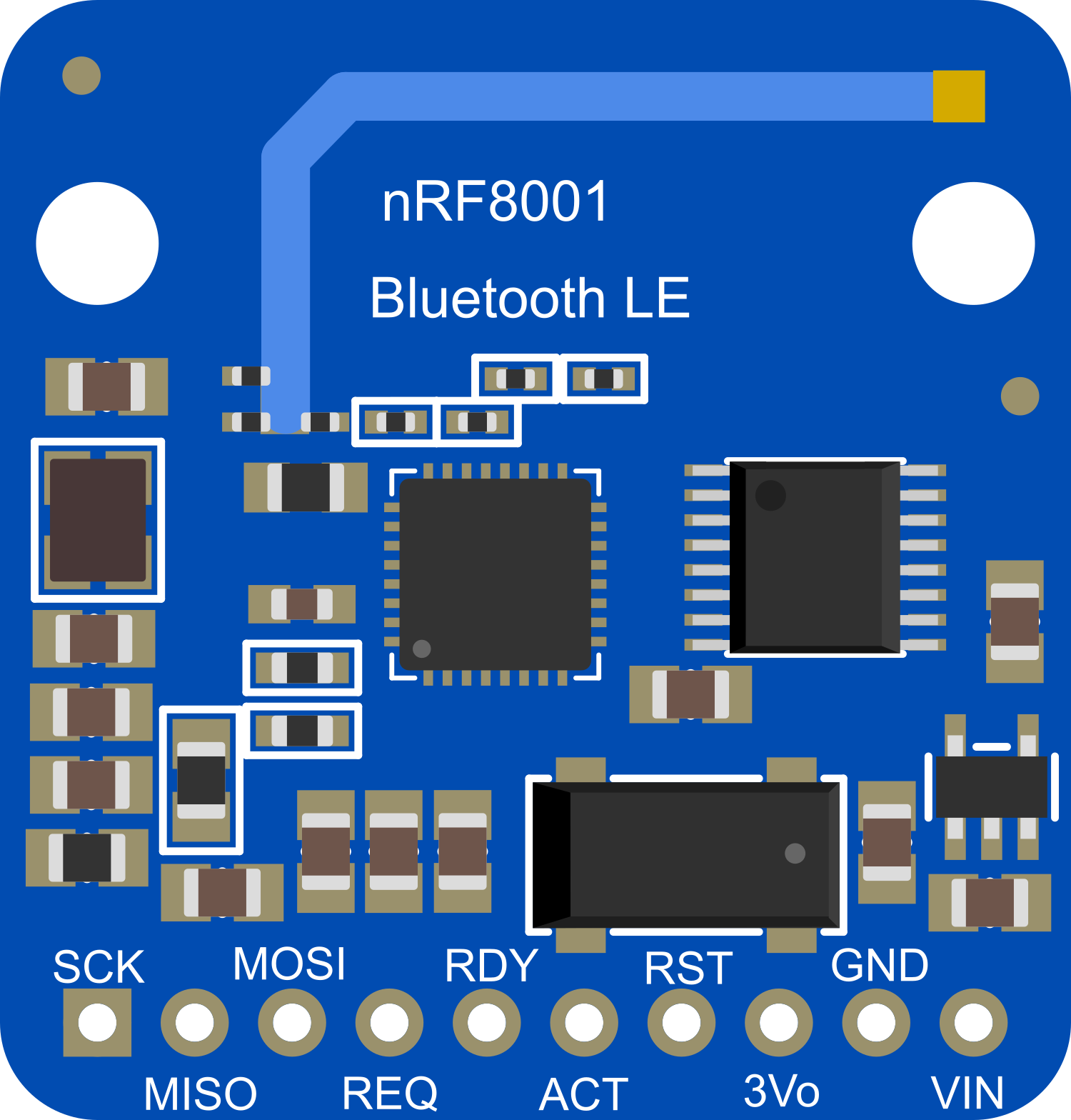
Pin Configuration and Descriptions

Pin Number Name Description
1 VIN Supply voltage (3.3V - 12V DC)
2 GND Ground
3 REQ SPI Chip Select / Request
4 RDY Ready pin, indicates data is available from nRF8001
5 RST Reset pin
6 SCK SPI Clock
7 MOSI SPI Master Out Slave In
8 MISO SPI Master In Slave Out
9 ACT Activity pin, indicates the radio is active

Usage Instructions

How to Use the Component in a Circuit

  1. Powering the Module: Connect the VIN pin to a 3.3V supply, and the GND pin to the ground of your power supply.
  2. SPI Communication: Connect the SCK, MOSI, and MISO pins to the corresponding SPI pins on your microcontroller.
  3. Control Pins: Connect the REQ, RDY, and RST pins to available digital I/O pins on your microcontroller.
  4. Activity Monitoring (Optional): Connect the ACT pin to an I/O pin if you wish to monitor the radio activity.

Important Considerations and Best Practices

  • Ensure that the power supply is clean and stable to prevent any damage to the module.
  • Use pull-up resistors on the REQ, RDY, and RST pins if your microcontroller does not have built-in pull-ups.
  • When using with a 5V microcontroller, ensure that the I/O pins are 5V tolerant or use level shifters.
  • Keep the antenna area of the nRF8001 breakout clear of metal and other materials that may interfere with the signal.

Example Code for Arduino UNO

#include <SPI.h>
#include <Adafruit_BLE_UART.h>

// Connect REQ to pin 10, RDY to pin 2, RST to pin 9
Adafruit_BLE_UART BTLESerial = Adafruit_BLE_UART(10, 2, 9);

void setup() {
  Serial.begin(9600);
  BTLESerial.begin();
}

void loop() {
  BTLESerial.pollACI();
  
  // If there's data available from the BLE module
  if (BTLESerial.available()) {
    char c = BTLESerial.read();
    Serial.print(c);
  }

  // If there's data available from the serial monitor
  if (Serial.available()) {
    char c = Serial.read();
    BTLESerial.write(c);
  }
}

Troubleshooting and FAQs

Common Issues

  • LEDs on the breakout are not lighting up: Ensure that the power supply is connected correctly and is within the specified voltage range.
  • No response from the module: Check that the SPI connections are correct and that the REQ, RDY, and RST pins are connected to the correct digital pins on your microcontroller.
  • Unable to pair with a device: Make sure the module is in range of the device and that there are no obstructions or interference sources nearby.

Solutions and Tips for Troubleshooting

  • Double-check all connections and ensure that solder joints are solid and not causing intermittent connections.
  • Use the serial monitor to debug and check for any error messages or status codes from the nRF8001 module.
  • Reset the module using the RST pin if it becomes unresponsive or behaves unexpectedly.

FAQs

Q: Can the nRF8001 Breakout be used with a 5V microcontroller? A: Yes, but ensure that the I/O pins are 5V tolerant or use level shifters to prevent damage to the module.

Q: What is the maximum range of the nRF8001 Breakout? A: The maximum range is approximately 60 feet (18 meters) in open space, but this can be reduced by obstacles and interference.

Q: Can I use the nRF8001 Breakout for streaming audio? A: No, the nRF8001 is designed for BLE and is not suitable for streaming audio. It is intended for low-bandwidth applications such as sensor data or control commands.