
How to Use LDR: Examples, Pinouts, and Specs
 Design with LDR in Cirkit Designer
Introduction
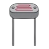
A Light Dependent Resistor (LDR), also known as a photoresistor, is a passive electronic component whose resistance decreases as the intensity of incident light increases. This property makes it an ideal choice for light sensing applications. LDRs are widely used in devices such as automatic streetlights, light meters, and alarm systems.
Explore Projects Built with LDR
 Open Project in Cirkit Designer
 Open Project in Cirkit Designer
 Open Project in Cirkit Designer
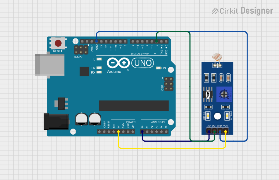 Open Project in Cirkit Designer
Explore Projects Built with LDR
Open Project in Cirkit DesignerOpen Project in Cirkit DesignerOpen Project in Cirkit DesignerOpen Project in Cirkit DesignerCommon Applications and Use Cases
- Automatic lighting systems (e.g., streetlights, garden lights)
- Light intensity measurement
- Alarm systems triggered by light changes
- Solar tracking systems
- Electronic toys and hobby projects
Technical Specifications
Below are the key technical details for the LDR manufactured by ARDUINO, part ID: UNO.
General Specifications
| Parameter | Value |
|---|---|
| Manufacturer | ARDUINO |
| Part ID | UNO |
| Resistance in Darkness | Typically > 1 MΩ |
| Resistance in Bright Light | Typically < 10 kΩ |
| Maximum Voltage | 150 V |
| Power Dissipation | 100 mW |
| Response Time | Rise: ~10 ms, Fall: ~30 ms |
| Operating Temperature | -30°C to +75°C |
Pin Configuration and Descriptions
The LDR is a two-terminal device with no polarity. The terminals can be connected in either direction. Below is a description of the pins:
| Pin Number | Pin Name | Description |
|---|---|---|
| 1 | Terminal 1 | Connects to one side of the circuit |
| 2 | Terminal 2 | Connects to the other side of the circuit |
Usage Instructions
How to Use the LDR in a Circuit
Basic Circuit Setup:
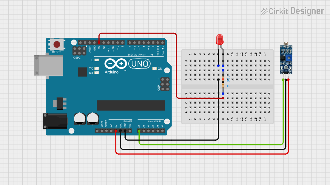
- Connect one terminal of the LDR to a voltage source (e.g., 5V from an Arduino UNO).
- Connect the other terminal to a resistor (typically 10 kΩ) in series, and then to ground.
- The junction between the LDR and the resistor serves as the output voltage point, which varies with light intensity.
Interfacing with Arduino UNO:
- Connect the output voltage point (junction of LDR and resistor) to an analog input pin on the Arduino UNO (e.g., A0).
- Use the Arduino's ADC (Analog-to-Digital Converter) to read the voltage and determine light intensity.
Important Considerations:
- Use a pull-down resistor to ensure stable readings.
- Avoid exposing the LDR to extreme temperatures or high-intensity light for prolonged periods, as this may degrade its performance.
- Shield the LDR from electrical noise for accurate readings.
Sample Arduino Code
Below is an example of how to use an LDR with an Arduino UNO to measure light intensity and display the readings in the Serial Monitor.
// Define the analog pin connected to the LDR
const int ldrPin = A0;

void setup() {
  Serial.begin(9600); // Initialize serial communication at 9600 baud
}

void loop() {
  int ldrValue = analogRead(ldrPin); // Read the analog value from the LDR
  float voltage = ldrValue * (5.0 / 1023.0); // Convert ADC value to voltage

  // Print the LDR value and voltage to the Serial Monitor
  Serial.print("LDR Value: ");
  Serial.print(ldrValue);
  Serial.print(" | Voltage: ");
  Serial.print(voltage);
  Serial.println(" V");

  delay(500); // Wait for 500 ms before the next reading
}
Best Practices
- Use a resistor value that matches the expected light conditions for optimal sensitivity.
- Place the LDR in a location where it can accurately sense the desired light source.
- If used outdoors, protect the LDR with a transparent cover to shield it from environmental damage.
Troubleshooting and FAQs
Common Issues and Solutions
Inconsistent Readings:
- Cause: Electrical noise or unstable connections.
- Solution: Use shorter wires, add a capacitor across the LDR terminals, or shield the circuit.
No Change in Output:
- Cause: Incorrect wiring or damaged LDR.
- Solution: Verify the connections and replace the LDR if necessary.
Output Saturates Quickly:
- Cause: Resistor value is too low or too high.
- Solution: Adjust the resistor value to better match the light conditions.
LDR Not Responding to Light:
- Cause: LDR exposed to extreme conditions or degraded over time.
- Solution: Replace the LDR and avoid exposing it to harsh environments.
FAQs
Q1: Can I use the LDR to measure precise light intensity?
A1: LDRs are suitable for relative light intensity measurements but are not ideal for precise or calibrated measurements. For precise applications, consider using a photodiode or light sensor module.
Q2: What resistor value should I use with the LDR?
A2: A 10 kΩ resistor is commonly used, but the value depends on the expected light conditions. Experiment with different resistor values to optimize sensitivity.
Q3: Can the LDR detect infrared light?
A3: LDRs are generally sensitive to visible light. For infrared detection, use an infrared photodiode or sensor.
Q4: Is the LDR polarity-sensitive?
A4: No, the LDR is not polarity-sensitive and can be connected in either direction.
By following this documentation, you can effectively integrate the ARDUINO LDR (part ID: UNO) into your projects for reliable light sensing applications.