Cirkit Designer Logo
Cirkit Designer
Your all-in-one circuit design IDE
Home / 
Component Documentation

How to Use Adafruit I2S Mic - SPH0645: Examples, Pinouts, and Specs

Image of Adafruit I2S Mic -  SPH0645
Cirkit Designer LogoDesign with Adafruit I2S Mic - SPH0645 in Cirkit Designer

Introduction

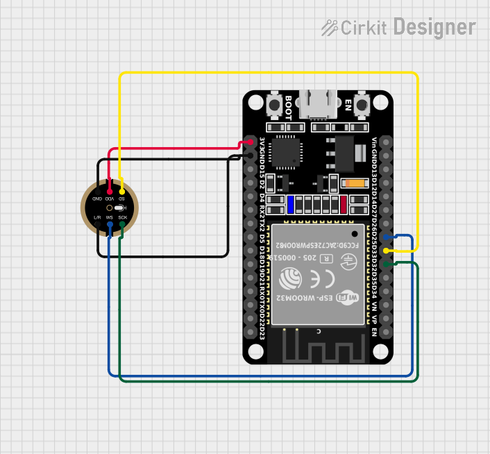
The Adafruit I2S Mic - SPH0645 is a high-quality MEMS microphone with an I2S (Inter-IC Sound) digital interface. This microphone is ideal for projects that require audio input, such as voice recognition, audio recording, and sound analysis. It is commonly used in conjunction with microcontrollers like the Arduino UNO, Raspberry Pi, and others that support I2S.

Explore Projects Built with Adafruit I2S Mic - SPH0645

Use Cirkit Designer to design, explore, and prototype these projects online. Some projects support real-time simulation. Click "Open Project" to start designing instantly!
ESP32-S3 and INMP441 I2S Microphone Audio Data Logger
Image of esp32-s3-DevKitC-1-N8R2-inmp441: A project utilizing Adafruit I2S Mic -  SPH0645 in a practical application
This circuit features an ESP32-S3-DevKitC-1-N8R2 microcontroller connected to an INMP441 microphone via I2S protocol. The ESP32 reads audio data from the microphone and prints it to the serial monitor, enabling real-time audio data acquisition and monitoring.
Cirkit Designer LogoOpen Project in Cirkit Designer
Raspberry Pi Zero-Based Audio Visualizer with OLED Display and INMP441 Microphone
Image of HEART_SOUND: A project utilizing Adafruit I2S Mic -  SPH0645 in a practical application
This circuit features a Raspberry Pi Zero connected to an INMP441 MEMS microphone and a 1.3" OLED display. The Raspberry Pi Zero communicates with the OLED display via I2C (using GPIO2 for SDA and GPIO3 for SCL), and it interfaces with the INMP441 microphone using I2S (with GPIO4 for SCK, GPIO9 for L/R selection, ID_SD for SD, and GPIO12 for WS). The circuit is designed for audio input through the microphone and visual output on the OLED display, likely for applications such as sound visualization or audio monitoring.
Cirkit Designer LogoOpen Project in Cirkit Designer
ESP32-Based I2S Digital Microphone Interface
Image of inmp441 mic with esp32: A project utilizing Adafruit I2S Mic -  SPH0645 in a practical application
This circuit connects an INMP441 MEMS microphone to an ESP32 microcontroller. The microphone's left/right (L/R) and ground (GND) pins are tied to the ESP32's ground, while its I2S interface pins (WS, SCK, SD) are connected to the ESP32's corresponding I2S pins (D25, D32, D33) for digital audio data transfer. The microphone is powered by the ESP32's 3.3V output.
Cirkit Designer LogoOpen Project in Cirkit Designer
ESP32 and INMP441 Microphone-Based Audio Capture System with Wi-Fi Connectivity
Image of inmp441 mic with esp32: A project utilizing Adafruit I2S Mic -  SPH0645 in a practical application
This circuit interfaces an INMP441 microphone with an ESP32 microcontroller. The ESP32 reads audio data from the microphone via I2S protocol, with connections for power, ground, and data lines (WS, SCK, SD) appropriately mapped between the two components.
Cirkit Designer LogoOpen Project in Cirkit Designer

Explore Projects Built with Adafruit I2S Mic - SPH0645

Use Cirkit Designer to design, explore, and prototype these projects online. Some projects support real-time simulation. Click "Open Project" to start designing instantly!
Image of esp32-s3-DevKitC-1-N8R2-inmp441: A project utilizing Adafruit I2S Mic -  SPH0645 in a practical application
ESP32-S3 and INMP441 I2S Microphone Audio Data Logger
This circuit features an ESP32-S3-DevKitC-1-N8R2 microcontroller connected to an INMP441 microphone via I2S protocol. The ESP32 reads audio data from the microphone and prints it to the serial monitor, enabling real-time audio data acquisition and monitoring.
Cirkit Designer LogoOpen Project in Cirkit Designer
Image of HEART_SOUND: A project utilizing Adafruit I2S Mic -  SPH0645 in a practical application
Raspberry Pi Zero-Based Audio Visualizer with OLED Display and INMP441 Microphone
This circuit features a Raspberry Pi Zero connected to an INMP441 MEMS microphone and a 1.3" OLED display. The Raspberry Pi Zero communicates with the OLED display via I2C (using GPIO2 for SDA and GPIO3 for SCL), and it interfaces with the INMP441 microphone using I2S (with GPIO4 for SCK, GPIO9 for L/R selection, ID_SD for SD, and GPIO12 for WS). The circuit is designed for audio input through the microphone and visual output on the OLED display, likely for applications such as sound visualization or audio monitoring.
Cirkit Designer LogoOpen Project in Cirkit Designer
Image of inmp441 mic with esp32: A project utilizing Adafruit I2S Mic -  SPH0645 in a practical application
ESP32-Based I2S Digital Microphone Interface
This circuit connects an INMP441 MEMS microphone to an ESP32 microcontroller. The microphone's left/right (L/R) and ground (GND) pins are tied to the ESP32's ground, while its I2S interface pins (WS, SCK, SD) are connected to the ESP32's corresponding I2S pins (D25, D32, D33) for digital audio data transfer. The microphone is powered by the ESP32's 3.3V output.
Cirkit Designer LogoOpen Project in Cirkit Designer
Image of inmp441 mic with esp32: A project utilizing Adafruit I2S Mic -  SPH0645 in a practical application
ESP32 and INMP441 Microphone-Based Audio Capture System with Wi-Fi Connectivity
This circuit interfaces an INMP441 microphone with an ESP32 microcontroller. The ESP32 reads audio data from the microphone via I2S protocol, with connections for power, ground, and data lines (WS, SCK, SD) appropriately mapped between the two components.
Cirkit Designer LogoOpen Project in Cirkit Designer

Technical Specifications

Key Technical Details

  • Interface: I2S
  • Supply Voltage: 1.6V to 3.6V
  • Current Consumption: 1.4 mA
  • Sensitivity: -26 dBFS (decibels relative to full scale)
  • Signal to Noise Ratio (SNR): 65 dB
  • Frequency Response: 100 Hz to 10 kHz
  • Output Data Rate: Adjustable up to 64 kHz

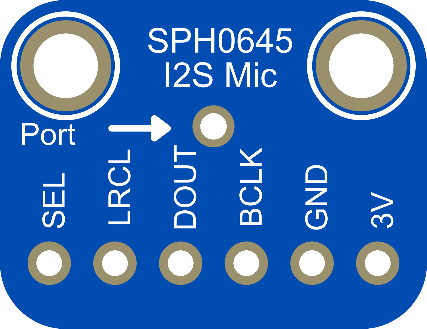
Pin Configuration and Descriptions

Pin Number Name Description
1 L/R Left/Right channel select
2 GND Ground connection
3 3Vo Output voltage (1.8V regulator output)
4 SCK Serial Clock for I2S
5 WS Word Select for I2S
6 SD Serial Data output for I2S
7 VIN Supply Voltage Input (1.6V to 3.6V)

Usage Instructions

Connecting to an Arduino UNO

  1. Power Connections:

    • Connect the VIN pin to the 3.3V output on the Arduino UNO.
    • Connect the GND pin to a ground pin on the Arduino UNO.
  2. I2S Connections:

    • Connect the SCK pin to the I2S clock pin on the Arduino (e.g., pin 13 on the Arduino UNO).
    • Connect the WS pin to the I2S word select pin on the Arduino (e.g., pin 10 on the Arduino UNO).
    • Connect the SD pin to the I2S data input pin on the Arduino (e.g., pin 11 on the Arduino UNO).
  3. Channel Selection:

    • The L/R pin can be connected to either GND or VIN to select the left or right channel, respectively.

Important Considerations and Best Practices

  • Ensure that the power supply is within the specified voltage range to prevent damage.
  • Use proper decoupling capacitors close to the power pins to minimize noise.
  • Keep the I2S signal lines as short as possible to reduce the risk of electromagnetic interference.
  • If using multiple I2S devices, ensure that each device has a unique word select (WS) line.

Example Arduino Code

#include <I2S.h>

// Define the I2S pins for the Arduino UNO
const int i2s_sck = 13;
const int i2s_ws = 10;
const int i2s_sd = 11;

void setup() {
  // Initialize I2S with the desired settings
  I2S.begin(I2S_PHILIPS_MODE, i2s_sck, i2s_ws, i2s_sd);
}

void loop() {
  // Read data from the microphone
  long sample = I2S.read();
  
  // Process the sample as needed
  // ...
}

Troubleshooting and FAQs

Common Issues

  • No Sound Detected: Ensure that the microphone is properly powered and that the I2S connections are correct.
  • Distorted Audio: Check for loose connections and ensure that the power supply is stable and within the specified range.
  • Low Volume: Verify that the microphone's orientation is correct and that it is not obstructed.

Solutions and Tips for Troubleshooting

  • Double-check all connections and solder joints for continuity and proper contact.
  • Use an oscilloscope to verify that the I2S clock and data lines are active.
  • Ensure that the Arduino library and board definitions support I2S and are up to date.

FAQs

Q: Can I use this microphone with a 5V microcontroller? A: Yes, but ensure that the VIN pin is connected to a 3.3V output, as the microphone is not 5V tolerant.

Q: How can I change the output data rate? A: The output data rate can be adjusted in the I2S.begin() function in the Arduino code.

Q: Is it possible to use two SPH0645 microphones for stereo recording? A: Yes, you can use two microphones by connecting them to separate I2S word select (WS) lines and configuring the L/R pin accordingly for each microphone.