How to Use Adafruit 1.2 Inch 8x8 LED Matrix Backpack Pure Green: Examples, Pinouts, and Specs
Introduction
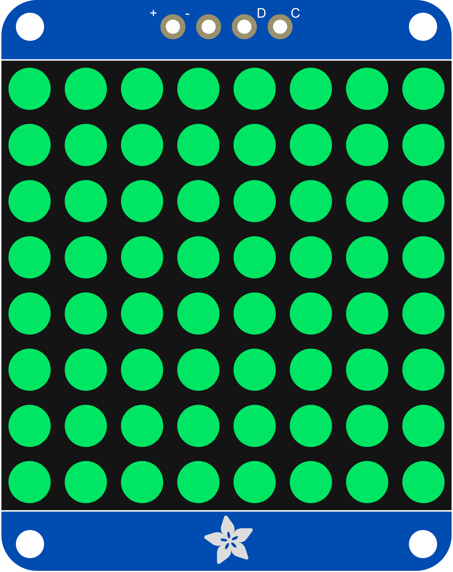
The Adafruit 1.2 Inch 8x8 LED Matrix Backpack Pure Green is a compact and versatile module designed for displaying graphical information in a simple and eye-catching way. This LED matrix is perfect for creating displays for counters, clocks, games, and various other applications where visual output is needed. The backpack simplifies the process of controlling multiple LEDs by consolidating the necessary circuitry into a single, easy-to-use package.
Explore Projects Built with Adafruit 1.2 Inch 8x8 LED Matrix Backpack Pure Green
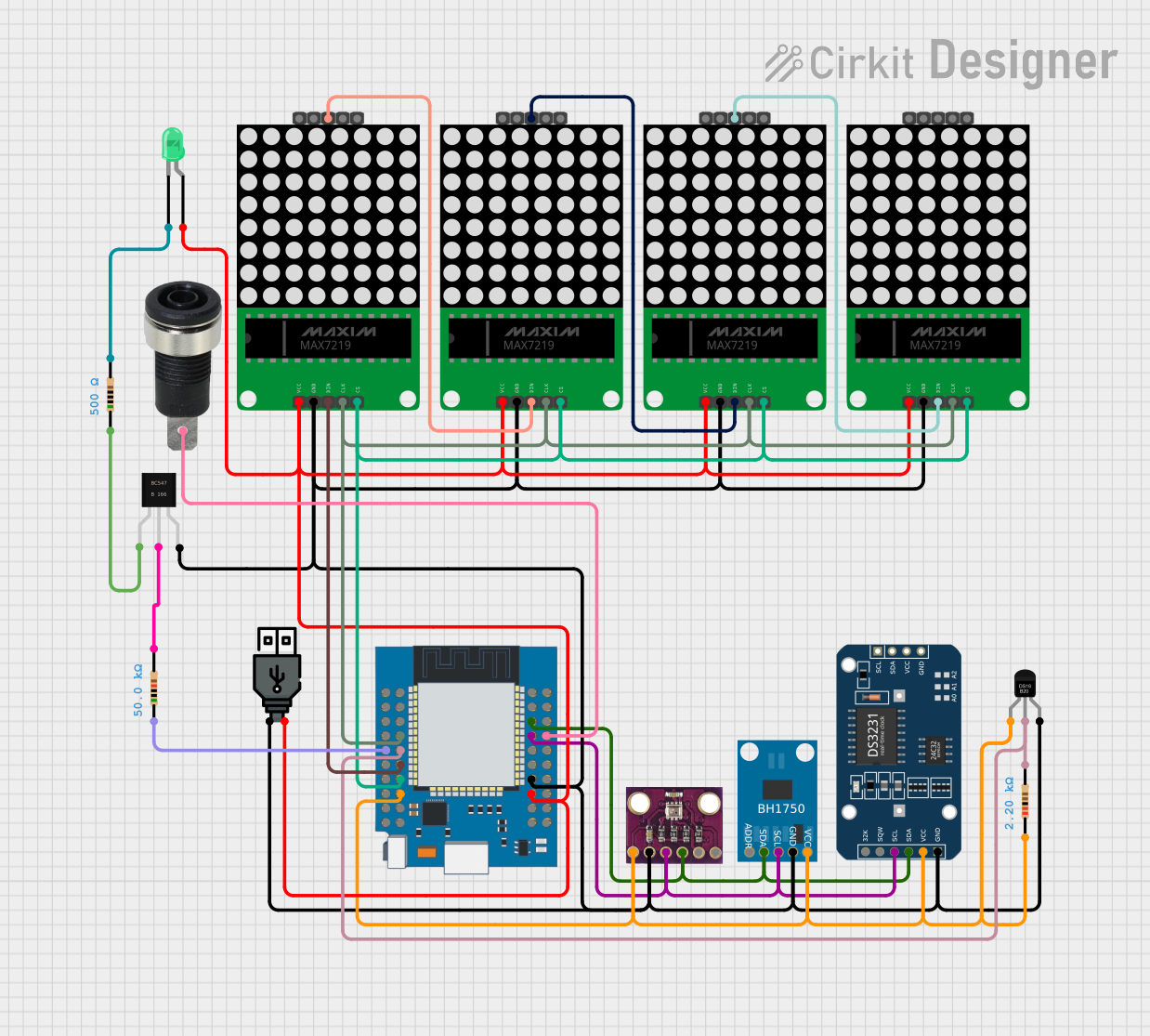


Explore Projects Built with Adafruit 1.2 Inch 8x8 LED Matrix Backpack Pure Green
Technical Specifications
Key Technical Details
- Display Color: Pure Green
- Matrix Size: 8x8 LEDs
- Dimensions: 1.2 inches (diagonal)
- Operating Voltage: 5V DC
- Max Current (all LEDs on): 320mA
- Interface: I2C
- I2C Addresses: Selectable via solder jumpers (0x70 - 0x77)
Pin Configuration and Descriptions
| Pin | Description |
|---|---|
| VCC | Connect to 5V power supply |
| GND | Connect to ground |
| SDA | I2C Data Line |
| SCL | I2C Clock Line |
Usage Instructions
Integrating with a Circuit
- Power Connections: Connect the VCC pin to a 5V supply, and the GND pin to the ground.
- I2C Connections: Connect the SDA and SCL pins to your microcontroller's I2C data and clock lines respectively.
- Address Selection: If using multiple LED matrices, set unique I2C addresses using the solder jumpers on the back.
Best Practices
- Ensure that the power supply can handle the maximum current draw when all LEDs are on.
- Use pull-up resistors on the I2C lines if they are not included in your microcontroller board.
- Avoid looking directly into the LEDs to prevent eye strain or damage.
Example Code for Arduino UNO
#include <Wire.h>
#include <Adafruit_GFX.h>
#include <Adafruit_LEDBackpack.h>

Adafruit_8x8matrix matrix = Adafruit_8x8matrix();

void setup() {
  matrix.begin(0x70); // Initialize the matrix with its I2C address
  matrix.setBrightness(10); // Set brightness level (0 is dim, 15 is bright)
}

void loop() {
  matrix.clear(); // Clear the matrix display
  matrix.drawPixel(4, 4, LED_ON); // Turn on a single LED (x=4, y=4)
  matrix.writeDisplay(); // Update the display with the changes
  delay(500); // Wait for half a second
  matrix.clear(); // Clear the display again
  matrix.writeDisplay(); // Update the display
  delay(500); // Wait for half a second
}
Troubleshooting and FAQs
Common Issues
- LEDs Not Lighting Up: Ensure that the power supply is connected correctly and the I2C lines are properly connected to the microcontroller.
- Dim LEDs: Check if the brightness is set too low in your code or if the power supply is insufficient.
- Garbled Display: Verify that the I2C address is correctly set and that there are no conflicts with other I2C devices.
FAQs
Q: Can I use this LED matrix with a 3.3V microcontroller? A: Yes, but ensure that the logic levels are compatible, and you may need level shifters for the I2C lines.
Q: How do I change the I2C address? A: Solder or desolder the jumpers on the back of the module to set the address you want.
Q: Can I daisy-chain multiple matrices? A: Yes, you can connect multiple matrices in series, but each must have a unique I2C address.
For further assistance, consult the Adafruit support forums or the product's FAQ section on the Adafruit website.