How to Use thermocouple: Examples, Pinouts, and Specs
Introduction
A thermocouple is a sensor used to measure temperature. It consists of two different types of metals joined at one end, which produce a voltage proportional to the temperature difference between the joined end and the other ends. Thermocouples are widely used in various applications due to their wide temperature range, durability, and relatively low cost.
Explore Projects Built with thermocouple

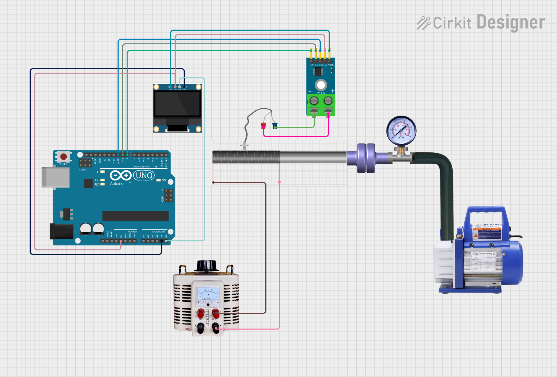
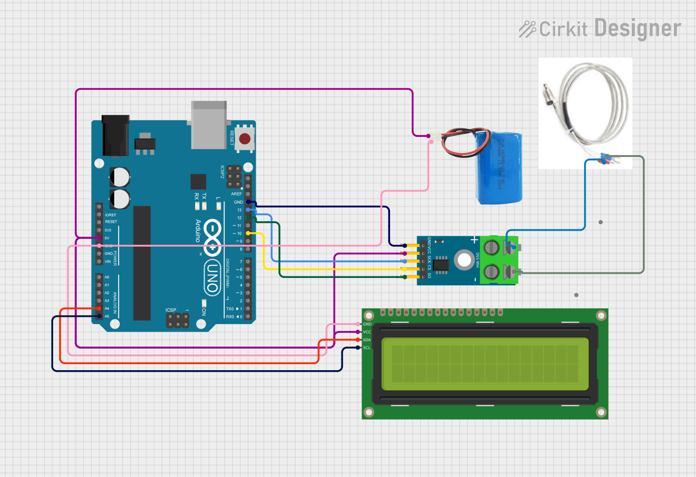
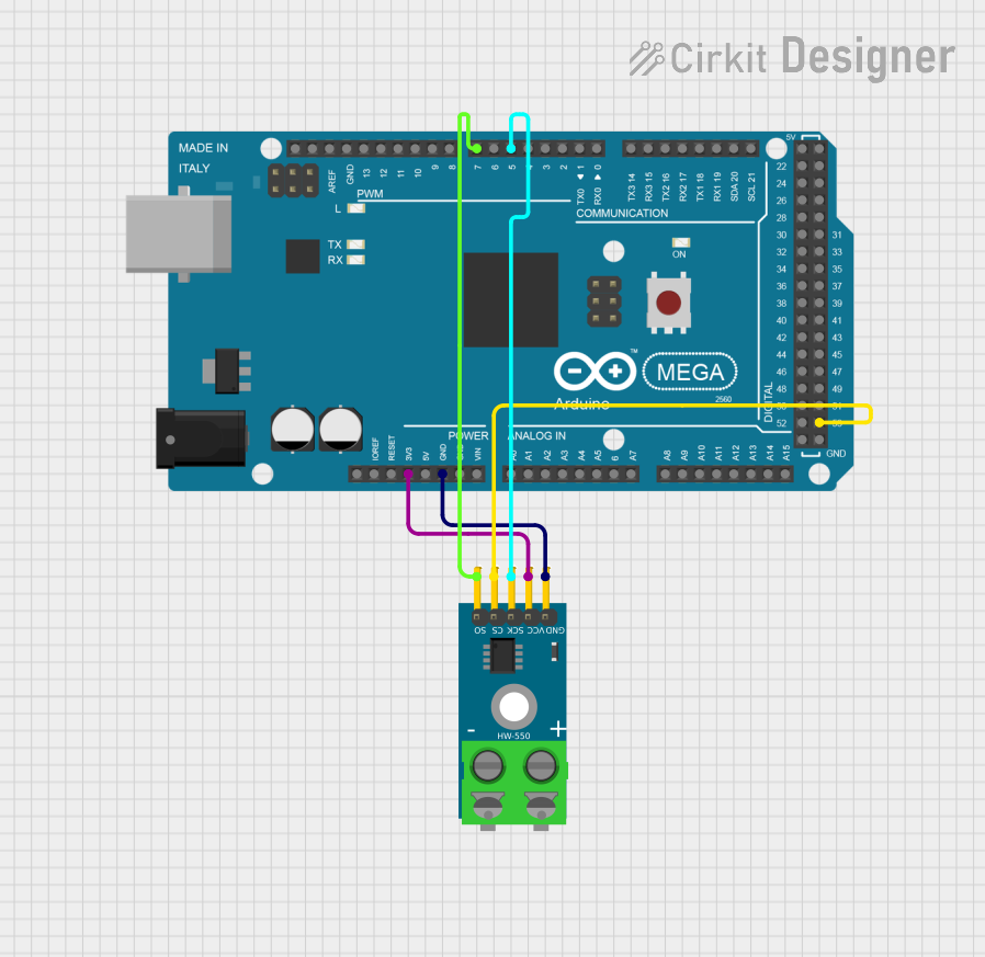
Explore Projects Built with thermocouple
Common Applications and Use Cases
- Industrial temperature monitoring
- HVAC systems
- Home appliances (e.g., ovens, water heaters)
- Automotive temperature sensing
- Scientific research and laboratory measurements
Technical Specifications
Key Technical Details
| Parameter | Value |
|---|---|
| Temperature Range | -200°C to 1350°C (Type K) |
| Voltage Output | 0 to 54.886 mV (Type K) |
| Accuracy | ±1.5°C or 0.4% (Type K) |
| Response Time | Typically 1 to 10 seconds |
| Insulation | Ceramic or fiberglass |
| Wire Material | Chromel and Alumel (Type K) |
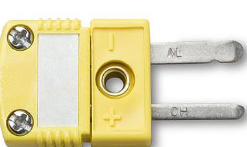
Pin Configuration and Descriptions
| Pin Number | Pin Name | Description |
|---|---|---|
| 1 | Positive | Chromel (Nickel-Chromium) |
| 2 | Negative | Alumel (Nickel-Aluminum) |
Usage Instructions
How to Use the Component in a Circuit
Connect the Thermocouple:
- Connect the positive pin (Chromel) to the positive input of your measurement device.
- Connect the negative pin (Alumel) to the negative input of your measurement device.
Amplify the Signal:
- Thermocouples produce a very small voltage, so an amplifier (e.g., MAX6675 or MAX31855) is often used to boost the signal to a readable level.
Read the Temperature:
- Use a microcontroller (e.g., Arduino UNO) to read the amplified signal and convert it to a temperature value.
Important Considerations and Best Practices
- Cold Junction Compensation: Thermocouples measure the temperature difference between the junction and the reference point. Ensure proper cold junction compensation for accurate readings.
- Shielding: Use shielded cables to minimize electrical noise interference.
- Calibration: Regularly calibrate your thermocouple to maintain accuracy.
- Placement: Place the thermocouple tip at the point where you want to measure the temperature for the most accurate readings.
Example Code for Arduino UNO
#include <SPI.h>
#include "Adafruit_MAX31855.h"

// Define the pins for the thermocouple amplifier
#define DO   3
#define CS   4
#define CLK  5

// Create an instance of the MAX31855 class
Adafruit_MAX31855 thermocouple(CLK, CS, DO);

void setup() {
  Serial.begin(9600);
  // Wait for serial port to connect. Needed for native USB
  while (!Serial) {
    delay(1);
  }
  Serial.println("MAX31855 Thermocouple Test");
}

void loop() {
  // Read the temperature in Celsius
  double celsius = thermocouple.readCelsius();
  if (isnan(celsius)) {
    Serial.println("Error: Could not read temperature!");
  } else {
    Serial.print("Temperature: ");
    Serial.print(celsius);
    Serial.println(" °C");
  }
  // Wait 1 second before reading again
  delay(1000);
}
Troubleshooting and FAQs
Common Issues Users Might Face
Inaccurate Readings:
- Solution: Ensure proper cold junction compensation and calibration. Check for electrical noise and use shielded cables.
No Output Signal:
- Solution: Verify connections and ensure the thermocouple is properly connected to the amplifier and microcontroller.
Fluctuating Readings:
- Solution: Check for loose connections and ensure the thermocouple is securely placed at the measurement point. Minimize electrical noise by using shielded cables.
FAQs
Q: Can I use a thermocouple without an amplifier? A: While it is possible, it is not recommended due to the very small voltage output of thermocouples. An amplifier like the MAX6675 or MAX31855 is typically used to boost the signal.
Q: How often should I calibrate my thermocouple? A: Calibration frequency depends on the application and usage conditions. For critical applications, regular calibration (e.g., monthly) is recommended.
Q: Can I extend the thermocouple wires? A: Yes, but use the same type of thermocouple wire to avoid introducing additional thermoelectric junctions that can affect accuracy.
Q: What is cold junction compensation? A: Cold junction compensation is a method to account for the temperature at the reference junction, ensuring accurate temperature readings.
By following this documentation, users can effectively utilize thermocouples in their projects, ensuring accurate and reliable temperature measurements.