How to Use bridge rectifier: Examples, Pinouts, and Specs
Introduction
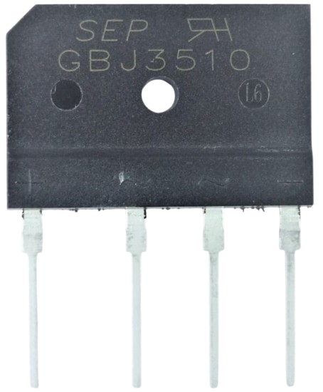
A bridge rectifier is an electrical circuit designed to convert alternating current (AC) into direct current (DC). It achieves this by using four diodes arranged in a bridge configuration, which allows current to flow in both directions while rectifying the AC input into a usable DC output. Bridge rectifiers are widely used in power supplies, battery charging circuits, and other applications requiring DC power derived from an AC source.
Explore Projects Built with bridge rectifier
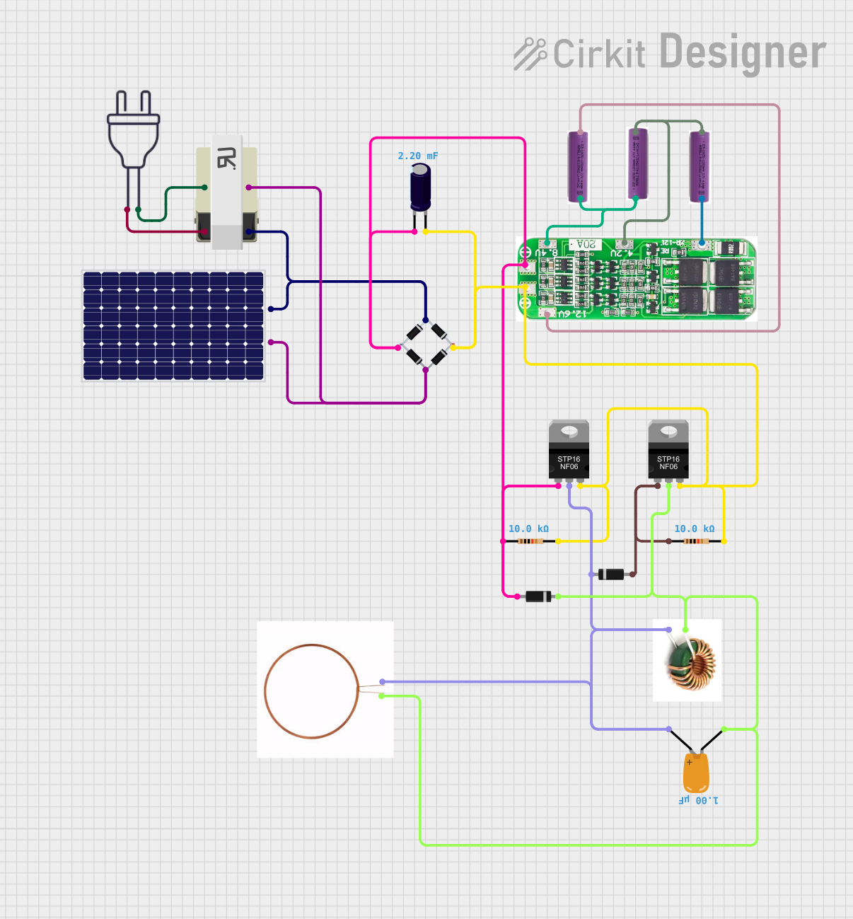
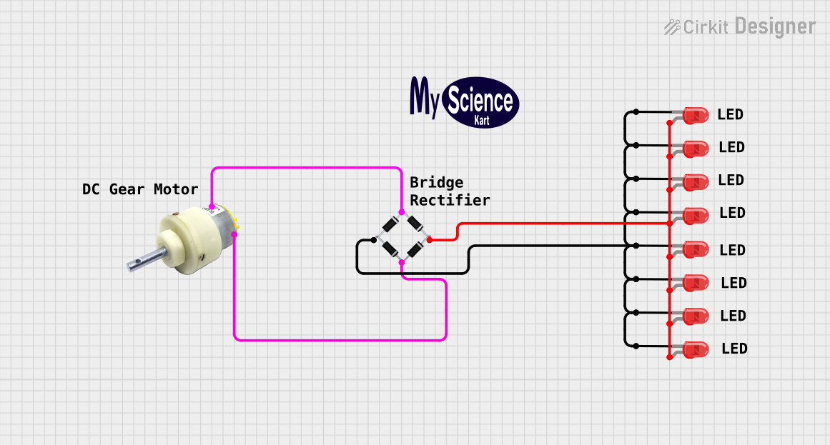
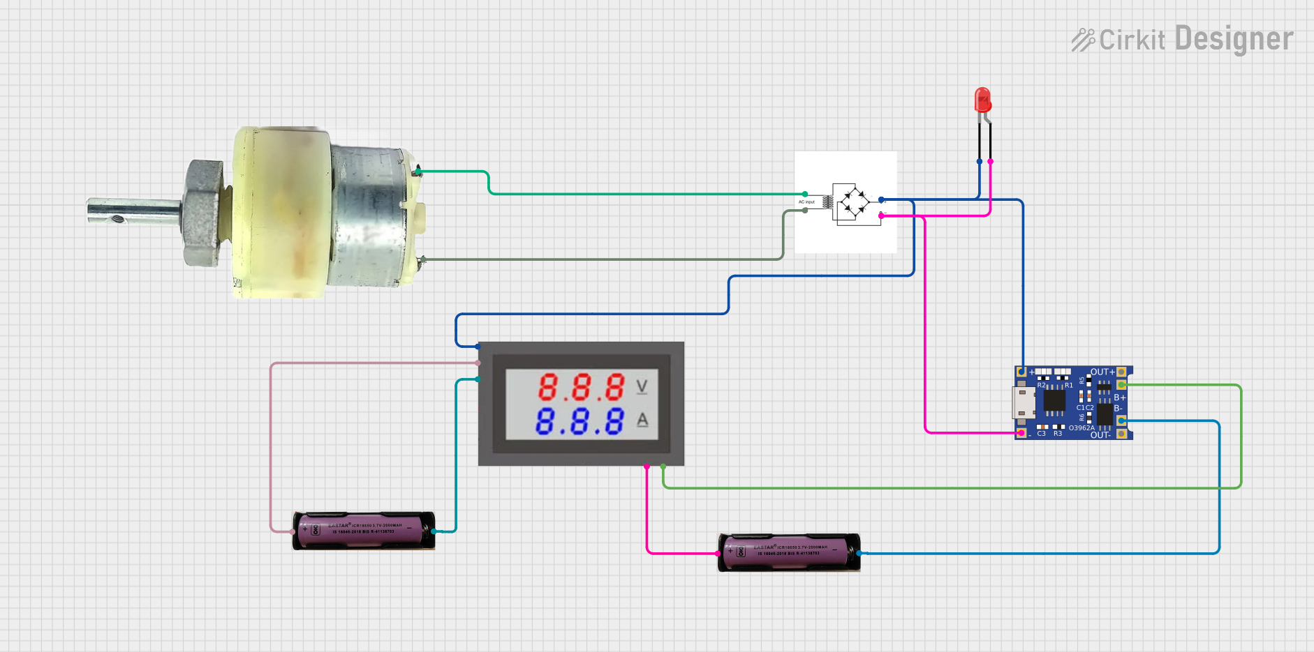
Explore Projects Built with bridge rectifier
Common Applications and Use Cases
- Power supplies for electronic devices
- Battery charging circuits
- DC motor drives
- LED lighting systems
- Rectification in renewable energy systems (e.g., solar panels, wind turbines)
Technical Specifications
Below are the general technical specifications for a typical bridge rectifier. Note that specific values may vary depending on the model and manufacturer.
Key Technical Details
- Input Voltage (AC): Typically ranges from 50V to 1000V (depending on the model)
- Output Voltage (DC): Approximately 0.9 × AC input voltage (after accounting for diode drops)
- Forward Voltage Drop: ~0.7V per diode (1.4V total for two diodes in series)
- Maximum Current Rating: 1A to 50A or more (varies by model)
- Reverse Voltage (PIV): Typically 100V to 1000V
- Efficiency: ~80-90% (depends on load and diode characteristics)
- Operating Temperature Range: -40°C to +125°C (varies by model)
Pin Configuration and Descriptions
The bridge rectifier typically has four terminals: two for the AC input and two for the DC output. The pin configuration is as follows:
| Pin Name | Description |
|---|---|
| AC Input (AC1) | First AC input terminal |
| AC Input (AC2) | Second AC input terminal |
| DC Output (+) | Positive DC output terminal |
| DC Output (-) | Negative DC output terminal (ground) |
The following diagram illustrates the pin configuration and internal diode arrangement:
       ~ AC1       ~ AC2
         |           |
         |           |
        [D1]       [D2]
         |           |
         +-----------+---- + DC Output
         |           |
        [D3]       [D4]
         |           |
         +-----------+---- - DC Output
Usage Instructions
How to Use the Component in a Circuit
- Connect the AC Input:
- Attach the AC source to the two AC input terminals (AC1 and AC2). Ensure the input voltage is within the rectifier's rated range.
- Connect the DC Output:
- Connect the positive DC output terminal (+) to the load's positive terminal.
- Connect the negative DC output terminal (-) to the load's ground or negative terminal.
- Add a Filter Capacitor (Optional):
- To smooth the rectified DC output, connect a capacitor (e.g., electrolytic capacitor) across the DC output terminals. The capacitor value depends on the load current and desired ripple voltage.
Important Considerations and Best Practices
- Heat Dissipation: High-current bridge rectifiers may generate significant heat. Use a heatsink or proper ventilation to prevent overheating.
- Reverse Voltage Protection: Ensure the peak inverse voltage (PIV) rating of the diodes exceeds the maximum AC input voltage to avoid damage.
- Fuse Protection: Add a fuse on the AC input side to protect the circuit from overcurrent conditions.
- Polarity: Double-check the polarity of the DC output connections to avoid damaging the load.
Example: Using a Bridge Rectifier with an Arduino UNO
If you are powering an Arduino UNO from an AC source, you can use a bridge rectifier to convert the AC to DC. Below is an example circuit and code to read the rectified voltage:
Circuit Setup
- Connect the AC source to the bridge rectifier's AC input terminals.
- Connect the DC output terminals to a voltage regulator (e.g., 7805) to provide a stable 5V output.
- Power the Arduino UNO using the regulated 5V output.
Arduino Code
// This code reads the rectified voltage using an analog pin on the Arduino UNO.
// Ensure the voltage divider reduces the input voltage to within 0-5V range.

const int voltagePin = A0; // Analog pin connected to the voltage divider
float voltage = 0.0;       // Variable to store the measured voltage

void setup() {
  Serial.begin(9600); // Initialize serial communication
}

void loop() {
  int sensorValue = analogRead(voltagePin); // Read the analog input
  voltage = sensorValue * (5.0 / 1023.0);   // Convert to voltage (0-5V range)

  // Print the measured voltage to the Serial Monitor
  Serial.print("Rectified Voltage: ");
  Serial.print(voltage);
  Serial.println(" V");

  delay(1000); // Wait for 1 second before the next reading
}
Troubleshooting and FAQs
Common Issues and Solutions
No Output Voltage:
- Cause: Incorrect wiring of the AC input or DC output terminals.
- Solution: Verify the connections and ensure the AC source is active.
Excessive Heat:
- Cause: Overcurrent or insufficient cooling.
- Solution: Check the load current and ensure it is within the rectifier's rated capacity. Add a heatsink if necessary.
High Ripple Voltage:
- Cause: Absence of a filter capacitor or insufficient capacitance.
- Solution: Add or increase the value of the filter capacitor across the DC output.
Damaged Diodes:
- Cause: Input voltage exceeds the PIV rating of the diodes.
- Solution: Replace the rectifier with one that has a higher PIV rating.
FAQs
Q: Can I use a bridge rectifier with a DC input?
A: No, a bridge rectifier is designed for AC input. Using a DC input may result in improper operation or damage.
Q: How do I calculate the required filter capacitor value?
A: Use the formula:
[
C = \frac{I}{f \cdot V_{ripple}}
]
Where (I) is the load current, (f) is the AC frequency, and (V_{ripple}) is the allowable ripple voltage.
Q: Can I use a bridge rectifier for high-frequency AC signals?
A: Standard bridge rectifiers are not suitable for high-frequency signals. Use fast-recovery or Schottky diodes for such applications.