
How to Use BLDC-SHIELD_IFX007T: Examples, Pinouts, and Specs
 Design with BLDC-SHIELD_IFX007T in Cirkit Designer
Introduction
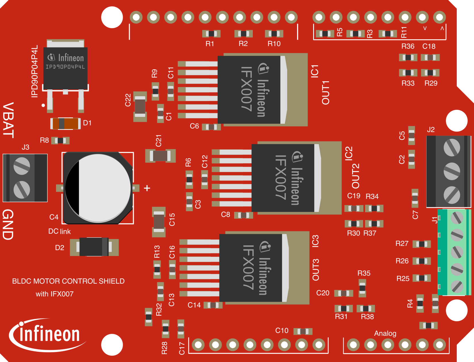
The BLDC-SHIELD_IFX007T is a motor driver shield developed by Infineon Technologies. It is specifically designed for controlling brushless DC (BLDC) motors and is compatible with Arduino platforms. This shield features integrated power management and protection circuits, making it ideal for applications requiring precise motor control, such as robotics, automation, and industrial systems.
The shield is based on the IFX007T half-bridge driver IC, which provides high efficiency, robust protection, and ease of use. It supports up to three-phase BLDC motors and offers features like overcurrent protection, overtemperature shutdown, and diagnostic feedback.
Explore Projects Built with BLDC-SHIELD_IFX007T
 Open Project in Cirkit Designer
 Open Project in Cirkit Designer
 Open Project in Cirkit Designer
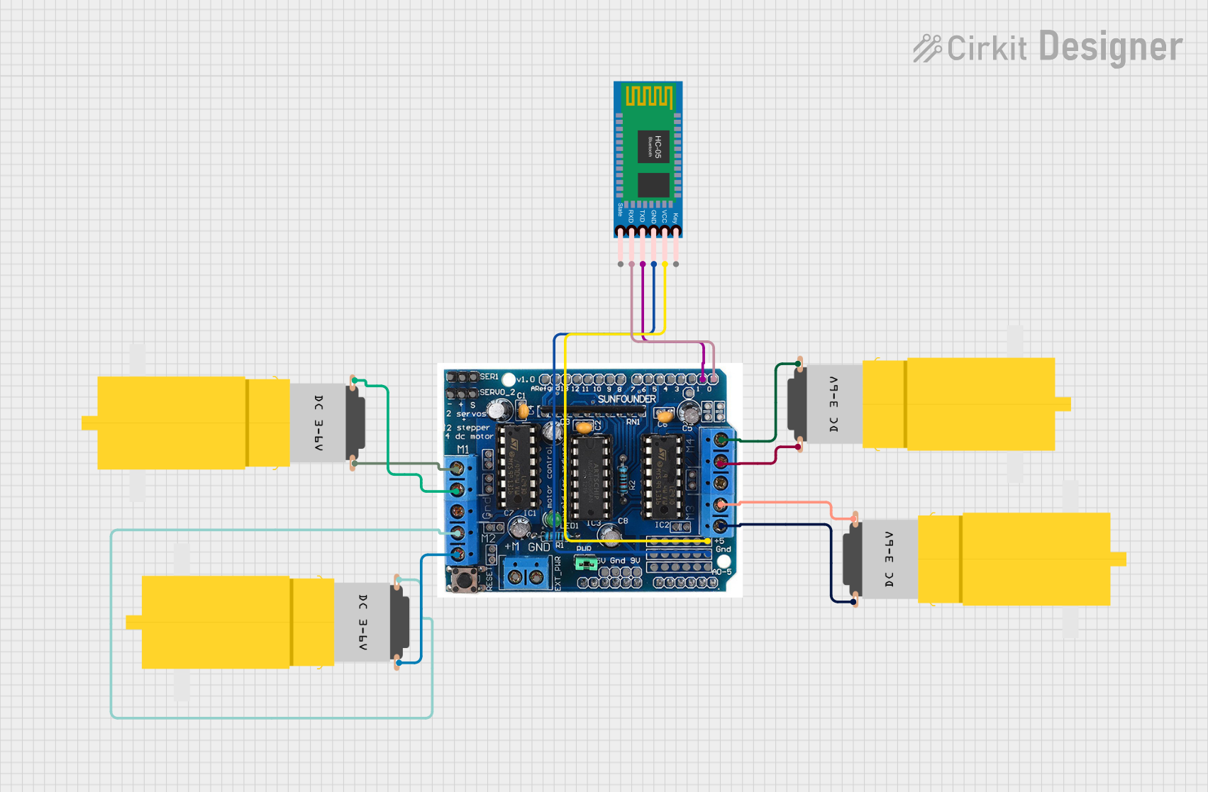 Open Project in Cirkit Designer
Explore Projects Built with BLDC-SHIELD_IFX007T
Open Project in Cirkit DesignerOpen Project in Cirkit DesignerOpen Project in Cirkit DesignerOpen Project in Cirkit DesignerCommon Applications
- Robotics and automation systems
- Industrial motor control
- Electric vehicles and drones
- Home appliances with BLDC motors
- Prototyping and educational projects
Technical Specifications
Key Technical Details
| Parameter | Value |
|---|---|
| Supply Voltage (Vcc) | 6 V to 18 V |
| Maximum Output Current | 6 A (continuous per phase) |
| Motor Type Supported | 3-phase Brushless DC (BLDC) motors |
| Communication Interface | PWM (Pulse Width Modulation) |
| Operating Temperature | -40°C to +125°C |
| Protection Features | Overcurrent, Overtemperature, Undervoltage |
| Dimensions | 73 mm x 53 mm |
Pin Configuration and Descriptions
The BLDC-SHIELD_IFX007T connects to an Arduino or similar microcontroller via its pin headers. Below is the pin configuration:
Arduino-Compatible Header Pins
| Pin Name | Description |
|---|---|
| VIN | External power supply input (6 V to 18 V) |
| GND | Ground connection |
| PWM_U | PWM input for phase U |
| PWM_V | PWM input for phase V |
| PWM_W | PWM input for phase W |
| EN | Enable pin for motor driver |
| DIAG | Diagnostic feedback pin |
Motor Output Terminals
| Terminal Name | Description |
|---|---|
| U | Motor phase U output |
| V | Motor phase V output |
| W | Motor phase W output |
Usage Instructions
How to Use the Component in a Circuit
- Power Supply: Connect an external power supply (6 V to 18 V) to the VIN and GND pins. Ensure the power supply can handle the current requirements of your motor.
- Motor Connection: Connect the three-phase BLDC motor to the U, V, and W output terminals.
- Microcontroller Connection: Attach the shield to an Arduino or compatible microcontroller. Ensure the PWM_U, PWM_V, and PWM_W pins are connected to PWM-capable pins on the microcontroller.
- Enable the Shield: Use the EN pin to enable or disable the motor driver. Pull the pin HIGH to enable the shield.
- Control the Motor: Use PWM signals on the PWM_U, PWM_V, and PWM_W pins to control the motor speed and direction.
Important Considerations and Best Practices
- Power Supply: Ensure the power supply voltage is within the specified range (6 V to 18 V). Using a voltage outside this range may damage the shield.
- Heat Dissipation: For high-current applications, ensure proper heat dissipation by using a heatsink or active cooling.
- PWM Frequency: Use a PWM frequency between 20 kHz and 25 kHz for optimal motor performance.
- Diagnostics: Monitor the DIAG pin for fault conditions such as overcurrent or overtemperature. A LOW signal on this pin indicates a fault.
Example Code for Arduino UNO
Below is an example Arduino sketch to control a BLDC motor using the BLDC-SHIELD_IFX007T:
// Example code to control a BLDC motor using BLDC-SHIELD_IFX007T
// Ensure the shield is properly connected to the Arduino UNO

// Define PWM pins for motor phases
#define PWM_U 9  // Connect to PWM_U pin on the shield
#define PWM_V 10 // Connect to PWM_V pin on the shield
#define PWM_W 11 // Connect to PWM_W pin on the shield

// Define Enable pin
#define ENABLE_PIN 8 // Connect to EN pin on the shield

void setup() {
  // Set PWM pins as output
  pinMode(PWM_U, OUTPUT);
  pinMode(PWM_V, OUTPUT);
  pinMode(PWM_W, OUTPUT);

  // Set Enable pin as output
  pinMode(ENABLE_PIN, OUTPUT);

  // Enable the motor driver
  digitalWrite(ENABLE_PIN, HIGH);
}

void loop() {
  // Example: Generate PWM signals to control the motor
  analogWrite(PWM_U, 128); // 50% duty cycle on phase U
  analogWrite(PWM_V, 64);  // 25% duty cycle on phase V
  analogWrite(PWM_W, 192); // 75% duty cycle on phase W

  delay(1000); // Run motor for 1 second

  // Stop the motor
  analogWrite(PWM_U, 0);
  analogWrite(PWM_V, 0);
  analogWrite(PWM_W, 0);

  delay(1000); // Wait for 1 second before restarting
}
Troubleshooting and FAQs
Common Issues and Solutions
Motor Does Not Spin:
- Ensure the power supply is connected and within the specified voltage range.
- Verify that the EN pin is pulled HIGH to enable the shield.
- Check the PWM signals from the microcontroller.
Overheating:
- Ensure proper heat dissipation using a heatsink or fan.
- Reduce the motor load or current if possible.
Diagnostic Pin Indicates a Fault:
- Check for overcurrent or overtemperature conditions.
- Verify that the motor is not stalled or overloaded.
PWM Signals Not Working:
- Ensure the microcontroller pins used for PWM are configured correctly.
- Verify the PWM frequency is within the recommended range (20 kHz to 25 kHz).
FAQs
Q: Can I use this shield with a 24 V motor?
A: No, the shield supports a maximum supply voltage of 18 V. Using a 24 V motor may damage the shield.
Q: Is the shield compatible with Arduino Mega?
A: Yes, the shield is compatible with Arduino Mega. Ensure the PWM pins are correctly mapped.
Q: How do I monitor faults using the DIAG pin?
A: Connect the DIAG pin to a digital input on your microcontroller. A LOW signal indicates a fault condition.
Q: Can I control multiple motors with this shield?
A: No, the shield is designed to control a single three-phase BLDC motor.
This concludes the documentation for the BLDC-SHIELD_IFX007T. For further details, refer to the official datasheet provided by Infineon Technologies.