How to Use Hiwonder 4-Channel IR Line Follower Sensor: Examples, Pinouts, and Specs
Introduction
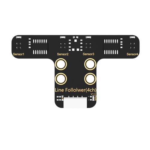
The Hiwonder 4-Channel IR Line Follower Sensor (Part ID: 9999) is a versatile sensor module designed for detecting lines on the ground using infrared (IR) light. It is commonly used in robotics applications to enable autonomous path-following capabilities. With its four independent IR channels, the sensor provides enhanced accuracy and flexibility, making it ideal for projects such as line-following robots, maze solvers, and automated guided vehicles (AGVs).
Explore Projects Built with Hiwonder 4-Channel IR Line Follower Sensor
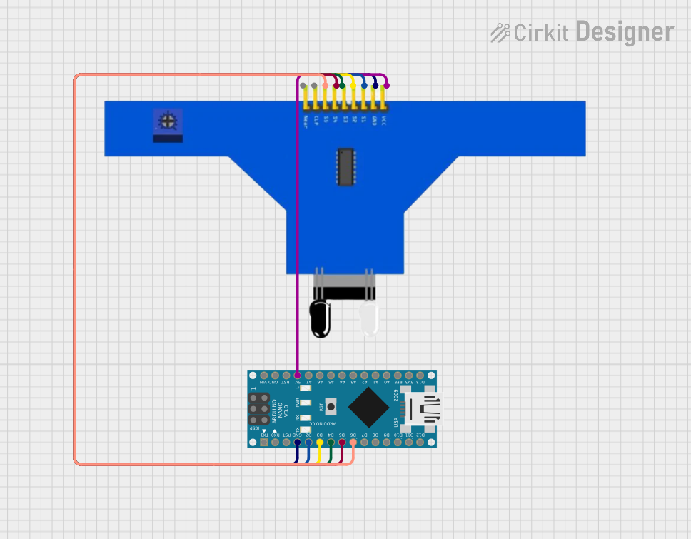
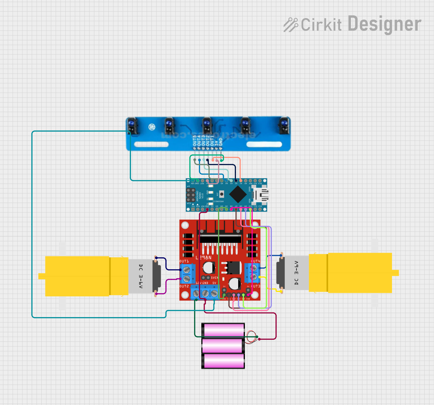
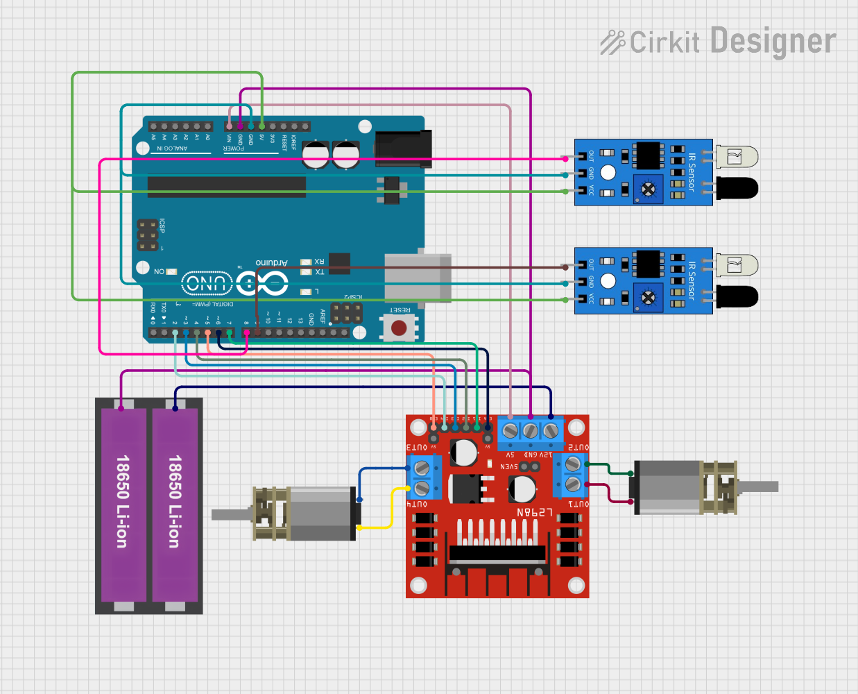

Explore Projects Built with Hiwonder 4-Channel IR Line Follower Sensor
Common Applications and Use Cases
- Line-following robots for educational and industrial purposes
- Maze-solving robots
- Automated guided vehicles (AGVs) for warehouse automation
- Path-following drones or rovers
- Obstacle detection and edge detection in robotics
Technical Specifications
The following table outlines the key technical details of the Hiwonder 4-Channel IR Line Follower Sensor:
| Parameter | Value |
|---|---|
| Operating Voltage | 3.3V to 5V |
| Operating Current | ≤ 20mA |
| Detection Range | 1mm to 12mm |
| Output Type | Digital (High/Low) |
| Number of Channels | 4 |
| IR Wavelength | 850nm |
| Dimensions | 70mm x 20mm x 10mm |
| Weight | 10g |
| Operating Temperature | -10°C to 50°C |
Pin Configuration and Descriptions
The Hiwonder 4-Channel IR Line Follower Sensor has a 6-pin interface. The pin configuration is as follows:
| Pin | Name | Description |
|---|---|---|
| 1 | VCC | Power supply input (3.3V to 5V) |
| 2 | GND | Ground connection |
| 3 | OUT1 | Digital output for Channel 1 (High/Low based on line detection) |
| 4 | OUT2 | Digital output for Channel 2 (High/Low based on line detection) |
| 5 | OUT3 | Digital output for Channel 3 (High/Low based on line detection) |
| 6 | OUT4 | Digital output for Channel 4 (High/Low based on line detection) |
Usage Instructions
How to Use the Component in a Circuit
- Power the Sensor: Connect the
VCCpin to a 3.3V or 5V power source and theGNDpin to the ground of your circuit. - Connect the Outputs: Connect the
OUT1,OUT2,OUT3, andOUT4pins to the digital input pins of your microcontroller (e.g., Arduino UNO). - Position the Sensor: Mount the sensor module on your robot or device, ensuring the IR sensors face the ground. The optimal distance between the sensor and the ground is 2mm to 10mm.
- Calibrate the Sensor: Test the sensor on a black line against a white background to ensure proper detection. Adjust the height or angle if necessary.
Important Considerations and Best Practices
- Surface Contrast: Ensure the line to be followed has a high contrast (e.g., black line on a white surface) for accurate detection.
- Ambient Light: Avoid using the sensor in environments with strong ambient IR light, as it may interfere with detection.
- Power Supply: Use a stable power source to prevent fluctuations that could affect sensor performance.
- Sensor Placement: Position the sensor so that all four channels are aligned perpendicular to the line for optimal detection.
Example Code for Arduino UNO
Below is an example Arduino sketch to read the outputs of the Hiwonder 4-Channel IR Line Follower Sensor and display the results in the Serial Monitor:
// Define the pins connected to the sensor outputs
#define OUT1_PIN 2  // Channel 1 output connected to digital pin 2
#define OUT2_PIN 3  // Channel 2 output connected to digital pin 3
#define OUT3_PIN 4  // Channel 3 output connected to digital pin 4
#define OUT4_PIN 5  // Channel 4 output connected to digital pin 5

void setup() {
  // Initialize serial communication for debugging
  Serial.begin(9600);

  // Set sensor pins as inputs
  pinMode(OUT1_PIN, INPUT);
  pinMode(OUT2_PIN, INPUT);
  pinMode(OUT3_PIN, INPUT);
  pinMode(OUT4_PIN, INPUT);
}

void loop() {
  // Read the sensor outputs
  int channel1 = digitalRead(OUT1_PIN);
  int channel2 = digitalRead(OUT2_PIN);
  int channel3 = digitalRead(OUT3_PIN);
  int channel4 = digitalRead(OUT4_PIN);

  // Print the sensor states to the Serial Monitor
  Serial.print("Channel 1: ");
  Serial.print(channel1);
  Serial.print(" | Channel 2: ");
  Serial.print(channel2);
  Serial.print(" | Channel 3: ");
  Serial.print(channel3);
  Serial.print(" | Channel 4: ");
  Serial.println(channel4);

  // Add a small delay for readability
  delay(100);
}
Troubleshooting and FAQs
Common Issues Users Might Face
Sensor Not Detecting Lines:
- Cause: Insufficient contrast between the line and the background.
- Solution: Use a darker line or a lighter background to improve contrast.
Inconsistent Readings:
- Cause: Sensor height is not optimal or the surface is uneven.
- Solution: Adjust the sensor height to 2mm-10mm and ensure the surface is flat.
All Outputs Stuck at High or Low:
- Cause: Faulty wiring or incorrect power supply.
- Solution: Double-check the wiring and ensure the power supply is within the specified range (3.3V to 5V).
Interference from Ambient Light:
- Cause: Strong IR light sources in the environment.
- Solution: Use the sensor in a controlled lighting environment or shield it from external IR sources.
Solutions and Tips for Troubleshooting
- Verify the connections to the microcontroller and ensure the pins are correctly assigned in the code.
- Test each channel individually by covering/uncovering the corresponding IR sensor.
- If the sensor is still not working, check for physical damage or dirt on the IR sensors and clean them gently if needed.
By following this documentation, you can effectively integrate the Hiwonder 4-Channel IR Line Follower Sensor into your projects and troubleshoot any issues that arise.