How to Use vc 02 module: Examples, Pinouts, and Specs
Introduction
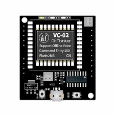
The VC 02 module is a versatile voltage control module designed to regulate and stabilize voltage levels in electronic circuits. It ensures that connected components operate within their optimal voltage range, protecting them from damage caused by voltage fluctuations. This module is widely used in power supply systems, battery-operated devices, and embedded systems where stable voltage is critical for reliable performance.
Explore Projects Built with vc 02 module


Explore Projects Built with vc 02 module
Common Applications and Use Cases
- Power supply regulation for microcontrollers and sensors
- Voltage stabilization in battery-powered devices
- Protection of sensitive electronic components from voltage spikes
- Use in embedded systems and IoT devices for consistent power delivery
Technical Specifications
The VC 02 module is designed to handle a wide range of input and output voltages, making it suitable for various applications. Below are its key technical specifications:
| Parameter | Value |
|---|---|
| Input Voltage Range | 4.5V to 30V |
| Output Voltage Range | 1.25V to 28V |
| Maximum Output Current | 2A |
| Efficiency | Up to 92% |
| Operating Temperature | -40°C to +85°C |
| Dimensions | 22mm x 17mm x 4mm |
Pin Configuration and Descriptions
The VC 02 module has a simple pinout for easy integration into circuits. Below is the pin configuration:
| Pin Name | Description |
|---|---|
| VIN | Input voltage pin. Connect the positive terminal of the input power source here. |
| GND | Ground pin. Connect the negative terminal of the input power source here. |
| VOUT | Output voltage pin. Provides the regulated output voltage. |
| ADJ | Adjustment pin. Used to set the desired output voltage using an external resistor or potentiometer. |
Usage Instructions
How to Use the VC 02 Module in a Circuit
Connect the Input Voltage:
- Connect the positive terminal of your power source to the
VINpin. - Connect the negative terminal of your power source to the
GNDpin.
- Connect the positive terminal of your power source to the
Set the Output Voltage:
- Use a potentiometer or resistor connected to the
ADJpin to adjust the output voltage. - Measure the output voltage at the
VOUTpin using a multimeter to ensure it matches your desired value.
- Use a potentiometer or resistor connected to the
Connect the Load:
- Connect the positive terminal of your load to the
VOUTpin. - Connect the negative terminal of your load to the
GNDpin.
- Connect the positive terminal of your load to the
Power On:
- Turn on the power source and verify the output voltage is stable before connecting sensitive components.
Important Considerations and Best Practices
- Ensure the input voltage is within the specified range (4.5V to 30V) to avoid damaging the module.
- Do not exceed the maximum output current of 2A to prevent overheating or failure.
- Use a heat sink or proper ventilation if the module operates at high currents for extended periods.
- Double-check all connections before powering on the module to avoid short circuits.
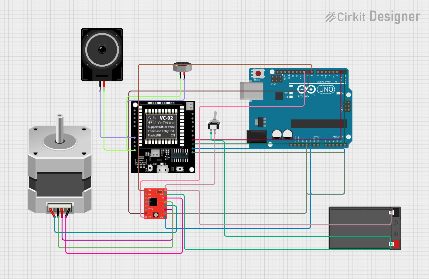
Example: Using the VC 02 Module with an Arduino UNO
The VC 02 module can be used to power an Arduino UNO by providing a stable 5V output. Below is an example setup:
- Connect a 9V battery to the
VINandGNDpins of the VC 02 module. - Adjust the
ADJpin to set the output voltage to 5V. - Connect the
VOUTpin of the module to the5Vpin of the Arduino UNO. - Connect the
GNDpin of the module to theGNDpin of the Arduino UNO.
Here is a simple Arduino code to blink an LED while powered by the VC 02 module:
// Simple LED Blink Example
// This code blinks an LED connected to pin 13 of the Arduino UNO.
// Ensure the VC 02 module provides a stable 5V to the Arduino.

void setup() {
  pinMode(13, OUTPUT); // Set pin 13 as an output pin
}

void loop() {
  digitalWrite(13, HIGH); // Turn the LED on
  delay(1000);            // Wait for 1 second
  digitalWrite(13, LOW);  // Turn the LED off
  delay(1000);            // Wait for 1 second
}
Troubleshooting and FAQs
Common Issues and Solutions
No Output Voltage:
- Cause: Incorrect input voltage or loose connections.
- Solution: Verify the input voltage is within the specified range and check all connections.
Output Voltage is Unstable:
- Cause: Insufficient input power or incorrect adjustment of the
ADJpin. - Solution: Ensure the input power source can supply sufficient current and re-adjust the
ADJpin.
- Cause: Insufficient input power or incorrect adjustment of the
Module Overheating:
- Cause: Exceeding the maximum output current or poor ventilation.
- Solution: Reduce the load current or add a heat sink to the module.
Output Voltage Does Not Match the Desired Value:
- Cause: Incorrect adjustment of the
ADJpin or faulty potentiometer. - Solution: Re-adjust the
ADJpin and replace the potentiometer if necessary.
- Cause: Incorrect adjustment of the
FAQs
Q: Can the VC 02 module be used with lithium-ion batteries?
A: Yes, the module can regulate voltage from lithium-ion batteries as long as the input voltage is within the specified range.
Q: Is the module protected against reverse polarity?
A: No, the VC 02 module does not have built-in reverse polarity protection. Always double-check the polarity of your connections.
Q: Can I use the module to power multiple devices simultaneously?
A: Yes, as long as the total current draw does not exceed 2A and the output voltage is suitable for all connected devices.
Q: How do I calculate the resistor value for the ADJ pin?
A: Refer to the module's datasheet for the formula to calculate the resistor value based on the desired output voltage.