How to Use LUX Sensor: Examples, Pinouts, and Specs
Introduction
A LUX sensor measures the intensity of light in a given environment, typically in lux units. It is widely used in applications such as automatic lighting control, environmental monitoring, and photography to ensure optimal lighting conditions. By converting light intensity into an electrical signal, the LUX sensor provides a reliable way to measure ambient light levels for various automation and monitoring systems.
Common applications include:
- Smart lighting systems that adjust brightness based on ambient light.
- Environmental monitoring for agriculture or greenhouses.
- Display brightness adjustment in electronic devices.
- Photography and videography for proper exposure settings.
Explore Projects Built with LUX Sensor
Explore Projects Built with LUX Sensor
Technical Specifications
Below are the general technical specifications for a typical LUX sensor. Note that specific models may vary slightly in their ratings.
| Parameter | Value |
|---|---|
| Operating Voltage | 3.0V to 5.5V |
| Operating Current | 0.5mA to 1mA |
| Measurement Range | 0.01 lux to 40,000 lux |
| Output Type | Analog or Digital (I2C) |
| Response Time | 100ms to 500ms |
| Operating Temperature | -40°C to +85°C |
| Accuracy | ±5% |
Pin Configuration and Descriptions
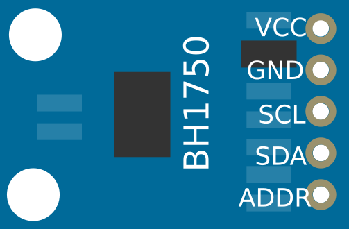
The pin configuration for a typical LUX sensor module (e.g., BH1750 or TSL2561) is as follows:
Analog LUX Sensor
| Pin Name | Description |
|---|---|
| VCC | Power supply input (3.0V to 5.5V) |
| GND | Ground connection |
| OUT | Analog output signal proportional to light intensity |
Digital LUX Sensor (I2C-based)
| Pin Name | Description |
|---|---|
| VCC | Power supply input (3.0V to 5.5V) |
| GND | Ground connection |
| SDA | Serial Data Line for I2C communication |
| SCL | Serial Clock Line for I2C communication |
| ADDR | Address selection pin (optional) |
Usage Instructions
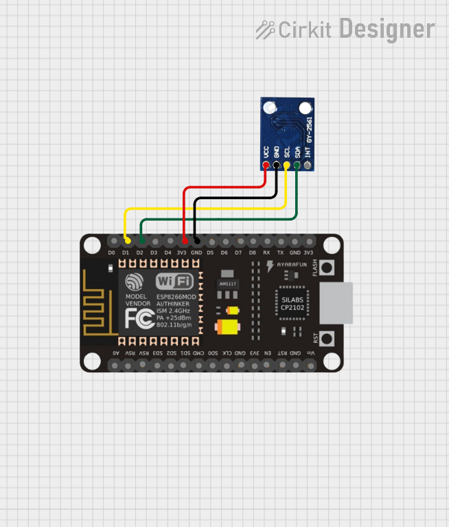
How to Use the LUX Sensor in a Circuit
- Power the Sensor: Connect the
VCCpin to a 3.3V or 5V power source and theGNDpin to ground. - Connect the Output:
- For analog sensors, connect the
OUTpin to an analog input pin on your microcontroller. - For digital (I2C) sensors, connect the
SDAandSCLpins to the corresponding I2C pins on your microcontroller.
- For analog sensors, connect the
- Pull-Up Resistors: For I2C sensors, ensure pull-up resistors (typically 4.7kΩ) are connected to the
SDAandSCLlines. - Read Data:
- For analog sensors, read the voltage on the
OUTpin and convert it to lux using the sensor's datasheet formula. - For digital sensors, use I2C communication to retrieve lux readings.
- For analog sensors, read the voltage on the
Important Considerations and Best Practices
- Avoid Direct Sunlight: Prolonged exposure to direct sunlight may damage the sensor or reduce its accuracy.
- Calibration: Some sensors may require calibration for precise measurements in specific environments.
- Noise Filtering: Use capacitors near the power pins to reduce noise and improve stability.
- I2C Address Conflicts: If using multiple I2C devices, ensure each has a unique address. Use the
ADDRpin to modify the address if needed.
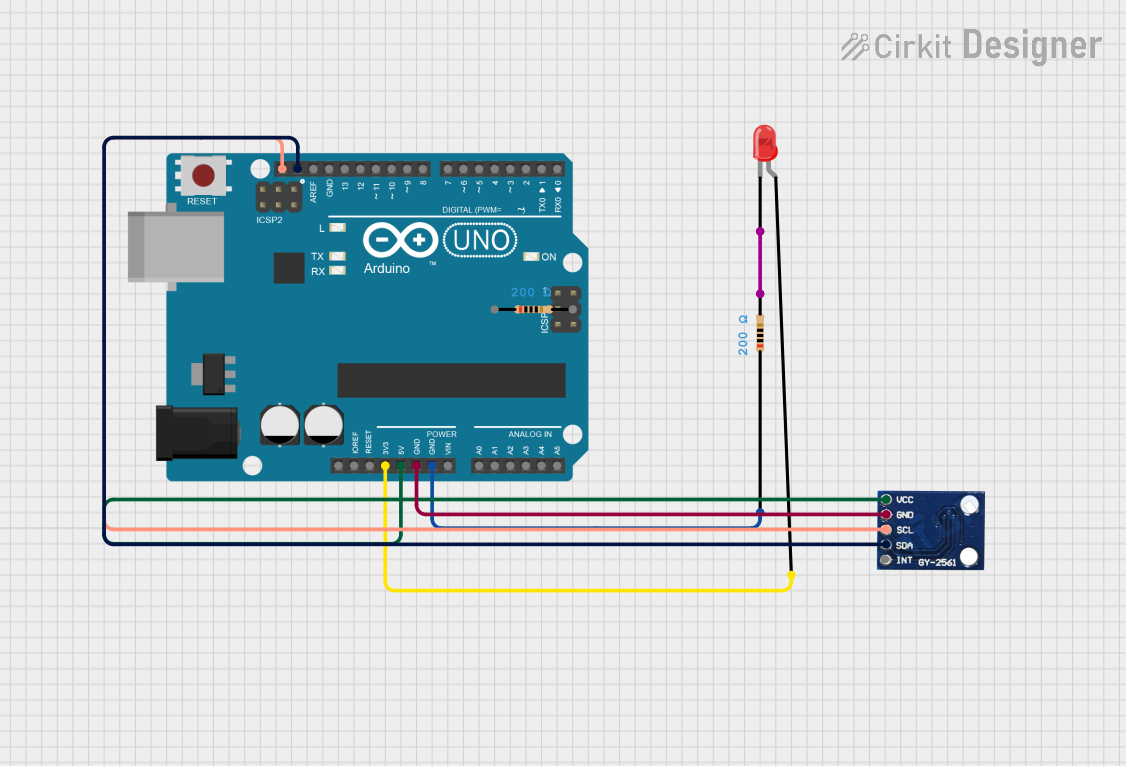
Example Code for Arduino UNO (I2C LUX Sensor)
Below is an example of how to use a BH1750 LUX sensor with an Arduino UNO:
#include <Wire.h>
#include <BH1750.h>

// Create an instance of the BH1750 sensor
BH1750 luxSensor;

void setup() {
  Serial.begin(9600); // Initialize serial communication at 9600 baud
  Wire.begin();       // Initialize I2C communication

  // Initialize the BH1750 sensor
  if (luxSensor.begin()) {
    Serial.println("BH1750 initialized successfully.");
  } else {
    Serial.println("Error initializing BH1750. Check connections.");
    while (1); // Halt execution if initialization fails
  }
}

void loop() {
  // Read light intensity in lux
  float lux = luxSensor.readLightLevel();

  // Print the lux value to the serial monitor
  Serial.print("Light Intensity: ");
  Serial.print(lux);
  Serial.println(" lux");

  delay(1000); // Wait for 1 second before the next reading
}
Notes:
- Install the
BH1750library in the Arduino IDE before uploading the code. - Adjust the
delay()value for faster or slower sampling rates.
Troubleshooting and FAQs
Common Issues
No Output or Incorrect Readings:
- Check the wiring and ensure all connections are secure.
- Verify that the power supply voltage matches the sensor's requirements.
- For I2C sensors, ensure pull-up resistors are present on the
SDAandSCLlines.
I2C Communication Failure:
- Confirm the I2C address of the sensor matches the address in your code.
- Use an I2C scanner sketch to detect the sensor's address.
Fluctuating or Noisy Readings:
- Add a decoupling capacitor (e.g., 0.1µF) near the sensor's power pins.
- Ensure the sensor is not exposed to sudden changes in light intensity.
FAQs
Q: Can I use the LUX sensor outdoors?
A: Yes, but ensure the sensor is protected from direct sunlight, rain, and extreme temperatures.
Q: How do I convert the analog output to lux?
A: Refer to the sensor's datasheet for the specific formula to convert voltage to lux. Typically, it involves a linear relationship.
Q: Can I use multiple LUX sensors with one microcontroller?
A: Yes, for I2C sensors, ensure each sensor has a unique address. For analog sensors, connect each to a separate analog input pin.
Q: What is the maximum distance for I2C communication?
A: I2C communication is reliable up to approximately 1 meter. For longer distances, consider using signal boosters or alternative communication protocols.
By following this documentation, you can effectively integrate and troubleshoot a LUX sensor in your projects.