How to Use DTMF Decoder: Examples, Pinouts, and Specs
Introduction
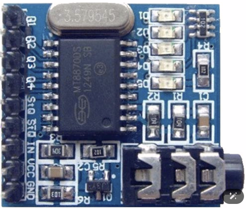
The MT8870, manufactured by Mitel Networks Corporation, is a DTMF (Dual-Tone Multi-Frequency) Decoder IC designed to detect and decode the audio tones generated by telephone keypads. It converts these tones into a 4-bit binary output, making it ideal for telecommunication systems, remote control applications, and interactive voice response (IVR) systems. The MT8870 is widely used in projects requiring tone-based signaling and control.
Explore Projects Built with DTMF Decoder
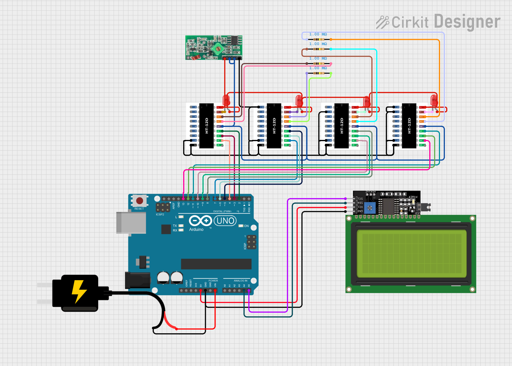

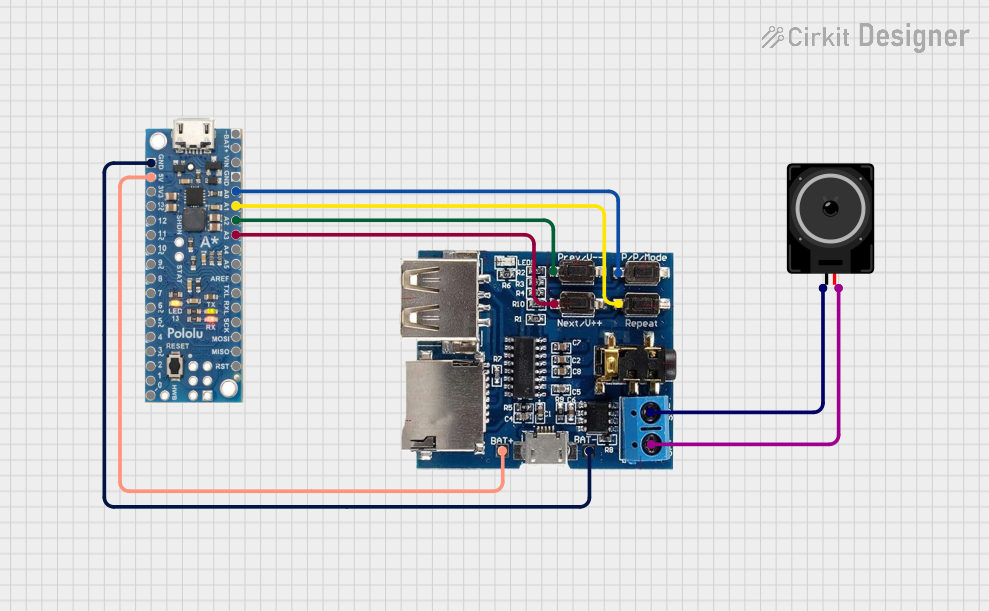
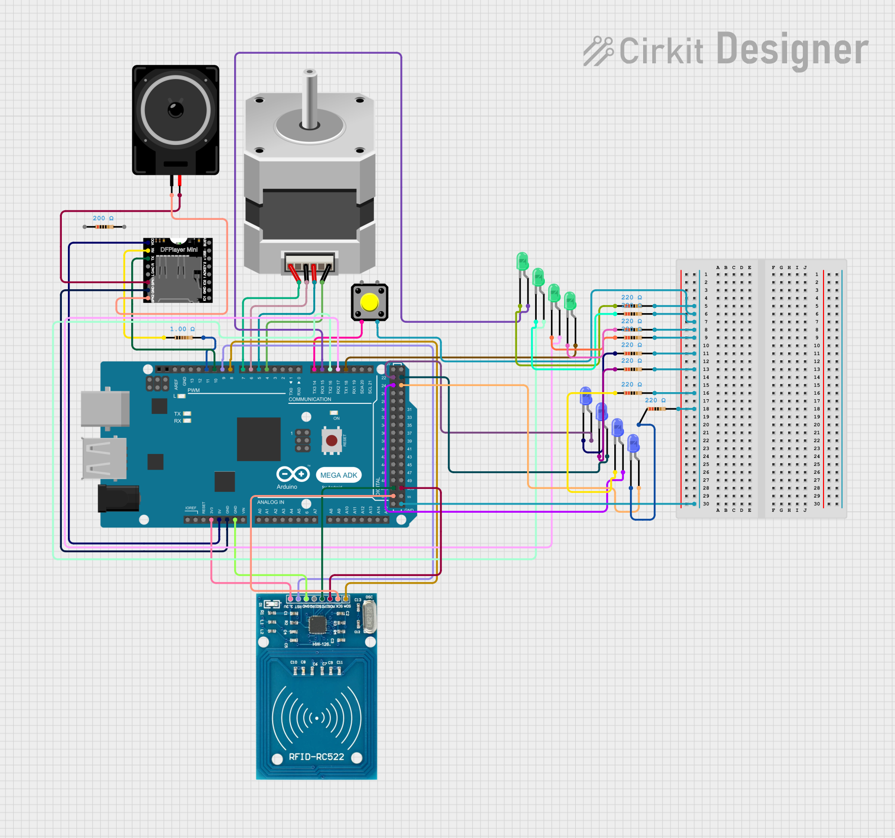
Explore Projects Built with DTMF Decoder
Common Applications
- Telephone-based remote control systems
- Interactive voice response (IVR) systems
- Caller ID systems
- Security systems with tone-based access
- Robotics and automation projects
Technical Specifications
Key Technical Details
- Operating Voltage: 4.75V to 5.25V DC
- Current Consumption: 3mA (typical)
- Input Signal Range: -35 dBm to +3 dBm
- Frequency Detection: Standard DTMF frequencies (low group: 697 Hz to 941 Hz, high group: 1209 Hz to 1633 Hz)
- Output: 4-bit binary code corresponding to the detected DTMF tone
- Operating Temperature: -40°C to +85°C
- Package Type: 18-pin DIP or SOIC
Pin Configuration and Descriptions
The MT8870 has 18 pins, each serving a specific function. The table below provides a detailed description of each pin:
| Pin Number | Pin Name | Description |
|---|---|---|
| 1 | IN+ | Non-inverting input for the DTMF signal. |
| 2 | IN- | Inverting input for the DTMF signal. |
| 3 | GS | Gain select pin for the input amplifier. |
| 4 | VREF | Reference voltage output. |
| 5 | INH | Inhibit pin. When high, it disables the detection of tones. |
| 6 | PWDN | Power-down mode. When high, it puts the IC into low-power mode. |
| 7 | OSC1 | Oscillator input. Connect to an external crystal or clock source. |
| 8 | OSC2 | Oscillator output. Connect to an external crystal or leave unconnected. |
| 9 | VSS | Ground (0V). |
| 10 | Q4 | 4th bit of the decoded binary output. |
| 11 | Q3 | 3rd bit of the decoded binary output. |
| 12 | Q2 | 2nd bit of the decoded binary output. |
| 13 | Q1 | 1st bit of the decoded binary output. |
| 14 | STD | Delayed steering output. Indicates when a valid DTMF tone pair is detected. |
| 15 | TOE | Three-state output enable. Controls the state of the binary output pins. |
| 16 | VDD | Positive supply voltage (+5V). |
| 17 | StD | Steering input. Used for tone detection timing. |
| 18 | St/GT | Steering input/output. Used for guard time adjustment. |
Usage Instructions
How to Use the MT8870 in a Circuit
- Power Supply: Connect the VDD pin to a regulated +5V DC supply and the VSS pin to ground.
- Input Signal: Feed the DTMF signal to the IN+ pin. If using differential input, connect the complementary signal to IN-. For single-ended input, connect IN- to ground.
- Oscillator: Connect a 3.579545 MHz crystal between OSC1 and OSC2. Add two 22pF capacitors to ground for stability.
- Output: The decoded 4-bit binary output is available on Q1 to Q4. Use the STD pin to check if a valid tone pair is detected.
- Steering Circuit: Connect a resistor and capacitor to the St/GT pin to set the tone detection guard time. Typical values are 300kΩ and 0.1µF.
Important Considerations
- Ensure the input signal is within the specified range (-35 dBm to +3 dBm) for accurate decoding.
- Use a low-noise power supply to avoid interference with the DTMF detection.
- The TOE pin can be used to enable or disable the binary output. When TOE is high, the output pins are in a high-impedance state.
- For applications requiring low power consumption, use the PWDN pin to put the IC into power-down mode.
Example: Connecting MT8870 to an Arduino UNO
Below is an example of how to interface the MT8870 with an Arduino UNO to read the decoded DTMF tones:
// Pin definitions for MT8870 connections
#define Q1 2  // Connect Q1 to Arduino digital pin 2
#define Q2 3  // Connect Q2 to Arduino digital pin 3
#define Q3 4  // Connect Q3 to Arduino digital pin 4
#define Q4 5  // Connect Q4 to Arduino digital pin 5
#define STD 6 // Connect STD to Arduino digital pin 6

void setup() {
  // Set MT8870 output pins as inputs
  pinMode(Q1, INPUT);
  pinMode(Q2, INPUT);
  pinMode(Q3, INPUT);
  pinMode(Q4, INPUT);
  pinMode(STD, INPUT);

  // Initialize serial communication for debugging
  Serial.begin(9600);
}

void loop() {
  // Check if a valid DTMF tone is detected
  if (digitalRead(STD) == HIGH) {
    // Read the 4-bit binary output
    int dtmfCode = (digitalRead(Q4) << 3) | (digitalRead(Q3) << 2) |
                   (digitalRead(Q2) << 1) | digitalRead(Q1);

    // Print the decoded DTMF code
    Serial.print("DTMF Code: ");
    Serial.println(dtmfCode, DEC);

    // Wait for the tone to end
    while (digitalRead(STD) == HIGH);
  }
}
Troubleshooting and FAQs
Common Issues and Solutions
No Output Detected:
- Ensure the input signal is within the specified range (-35 dBm to +3 dBm).
- Verify the crystal oscillator is functioning correctly (check connections to OSC1 and OSC2).
- Check the power supply voltage (should be 5V DC).
Incorrect Decoding:
- Verify the resistor and capacitor values connected to the St/GT pin.
- Ensure the input signal is not distorted or noisy.
Output Pins Always High or Low:
- Check the TOE pin. If it is high, the output pins will be in a high-impedance state.
- Verify the connections to the Q1-Q4 pins.
FAQs
Can the MT8870 decode custom frequencies?
- No, the MT8870 is designed to decode standard DTMF frequencies only.
What is the purpose of the STD pin?
- The STD pin indicates when a valid DTMF tone pair is detected. It can be used to trigger external circuits or microcontrollers.
Can the MT8870 operate at voltages other than 5V?
- No, the MT8870 requires a regulated 5V DC supply for proper operation.
How do I adjust the tone detection timing?
- The tone detection timing can be adjusted by changing the resistor and capacitor values connected to the St/GT pin.