How to Use Micro USB + adaptor: Examples, Pinouts, and Specs
Introduction
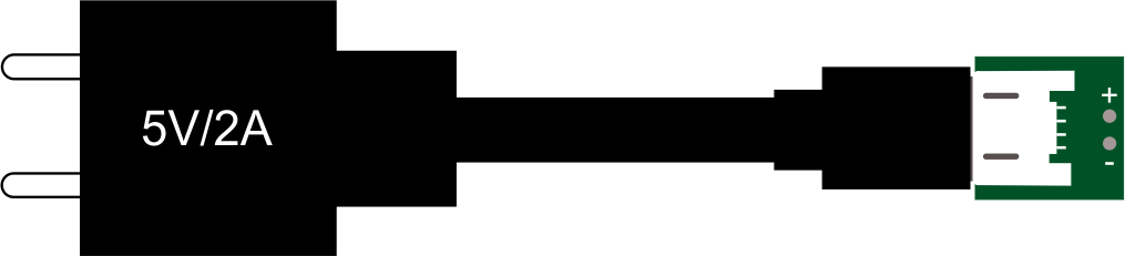
The Micro USB + Adaptor is a compact and versatile electronic component designed for charging and data transfer applications. The Micro USB connector is widely used in smartphones, tablets, power banks, and other portable devices due to its small size and reliable performance. The included adaptor enhances compatibility by allowing the Micro USB interface to connect with other USB standards, such as USB Type-A or USB Type-C, making it a flexible solution for various connectivity needs.
Explore Projects Built with Micro USB + adaptor


Explore Projects Built with Micro USB + adaptor
Common Applications and Use Cases
- Charging portable devices such as smartphones, tablets, and power banks.
- Data transfer between devices, including computers, external storage, and mobile devices.
- Adapting Micro USB devices to work with USB Type-A or USB Type-C ports.
- Prototyping and development in electronics projects requiring USB connectivity.
Technical Specifications
Key Technical Details
| Parameter | Specification |
|---|---|
| Connector Type | Micro USB (Type-B) |
| Adaptor Compatibility | USB Type-A, USB Type-C |
| Voltage Rating | 5V DC (standard USB voltage) |
| Current Rating | Up to 2.4A (depending on cable quality) |
| Data Transfer Speed | Up to 480 Mbps (USB 2.0 standard) |
| Operating Temperature | -20°C to 60°C |
| Durability | 10,000+ plug/unplug cycles |
Pin Configuration and Descriptions
Micro USB Pinout
| Pin Number | Name | Description |
|---|---|---|
| 1 | VBUS | Power supply (5V DC) |
| 2 | D- | Data line (-) for USB communication |
| 3 | D+ | Data line (+) for USB communication |
| 4 | ID | Identification pin (used in OTG devices) |
| 5 | GND | Ground |
USB Type-A Adaptor Pinout
| Pin Number | Name | Description |
|---|---|---|
| 1 | VBUS | Power supply (5V DC) |
| 2 | D- | Data line (-) for USB communication |
| 3 | D+ | Data line (+) for USB communication |
| 4 | GND | Ground |
Usage Instructions
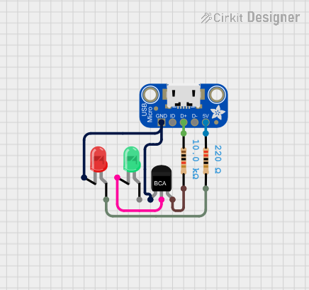
How to Use the Component in a Circuit
- Power Supply: Connect the VBUS pin of the Micro USB connector to a 5V DC power source. Ensure the current rating of the source matches the requirements of your device.
- Data Transfer: Use the D+ and D- pins for data communication. These pins should be connected to the corresponding data lines of the device or microcontroller.
- Adaptor Usage: Attach the adaptor to the Micro USB connector to enable compatibility with USB Type-A or USB Type-C ports. Ensure the adaptor is securely connected to avoid data or power interruptions.
Important Considerations and Best Practices
- Cable Quality: Use high-quality cables to ensure reliable power delivery and data transfer. Low-quality cables may cause voltage drops or data errors.
- Current Rating: Verify that the connected power source can supply sufficient current for your device. Overloading the power source may cause damage.
- Orientation: The Micro USB connector is not reversible. Ensure proper orientation when plugging it in to avoid damaging the connector or port.
- OTG Functionality: If using the Micro USB connector for On-The-Go (OTG) applications, ensure the ID pin is correctly configured for the intended use.
Example: Connecting to an Arduino UNO
The Micro USB + Adaptor can be used to power an Arduino UNO or transfer data via a USB-to-serial interface. Below is an example of Arduino code for serial communication:
// Example: Serial communication using Arduino UNO
// Ensure the Micro USB + Adaptor is connected to the Arduino's USB port

void setup() {
  Serial.begin(9600); // Initialize serial communication at 9600 baud
  Serial.println("Micro USB + Adaptor Test"); // Print a test message
}

void loop() {
  if (Serial.available() > 0) {
    // Read incoming data from the serial monitor
    char received = Serial.read();
    // Echo the received data back to the serial monitor
    Serial.print("Received: ");
    Serial.println(received);
  }
}
Troubleshooting and FAQs
Common Issues and Solutions
Device Not Charging
- Cause: Faulty cable or insufficient power supply.
- Solution: Check the cable for damage and ensure the power source meets the required voltage and current ratings.
Data Transfer Fails
- Cause: Loose connection or incompatible adaptor.
- Solution: Ensure the Micro USB connector and adaptor are securely connected. Verify that the adaptor is compatible with the device.
Overheating
- Cause: Excessive current draw or poor ventilation.
- Solution: Use a power source with appropriate current capacity. Avoid using the component in high-temperature environments.
Connector Damage
- Cause: Improper insertion or excessive force.
- Solution: Always insert the connector gently and in the correct orientation.
FAQs
Q: Can the Micro USB + Adaptor be used for fast charging?
A: The component supports up to 2.4A current, which is sufficient for standard fast charging. However, compatibility depends on the connected device and power source.
Q: Is the adaptor reversible?
A: The USB Type-C adaptor is reversible, but the Micro USB connector is not. Ensure proper orientation when connecting.
Q: Can this component be used for OTG applications?
A: Yes, the Micro USB connector includes an ID pin for OTG functionality. Ensure the connected device supports OTG.
Q: What is the maximum data transfer speed?
A: The component supports up to 480 Mbps, which is the standard for USB 2.0.