How to Use Quadruple Half-H Drivers: Examples, Pinouts, and Specs
Introduction
The L293D is a Quadruple Half-H Driver IC manufactured by Texas Instruments. It is designed to provide bidirectional current control for DC motors and other inductive loads. The IC contains four independent half-H drivers, which can be used to control the direction and speed of up to two DC motors or a single stepper motor. The L293D is widely used in robotics, motor control systems, and other applications requiring efficient power switching.
Explore Projects Built with Quadruple Half-H Drivers
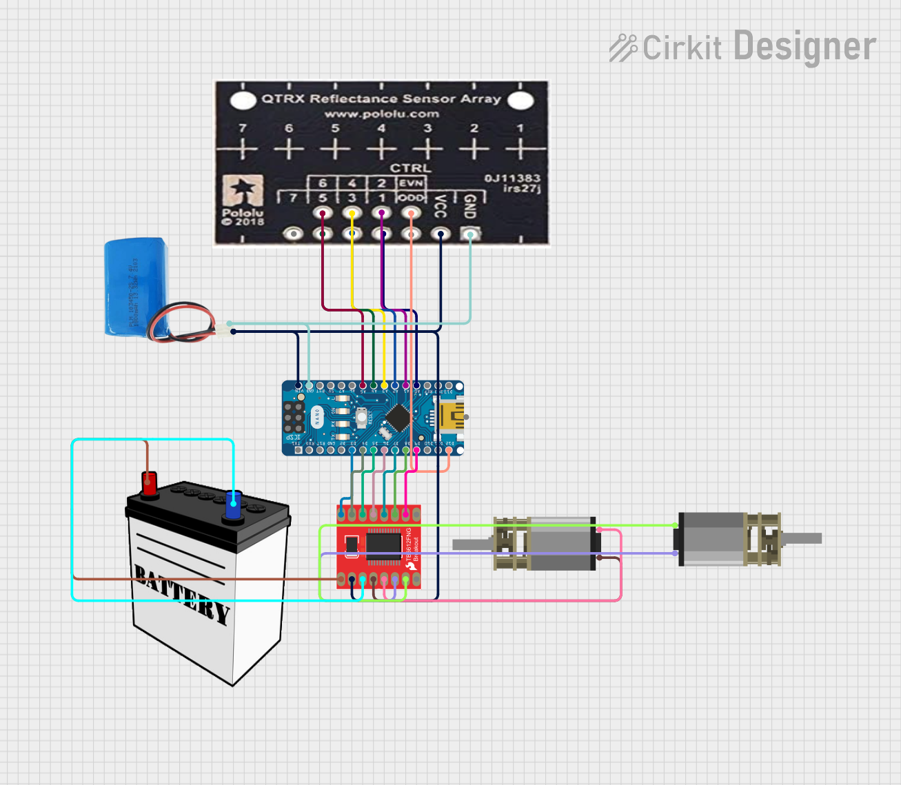

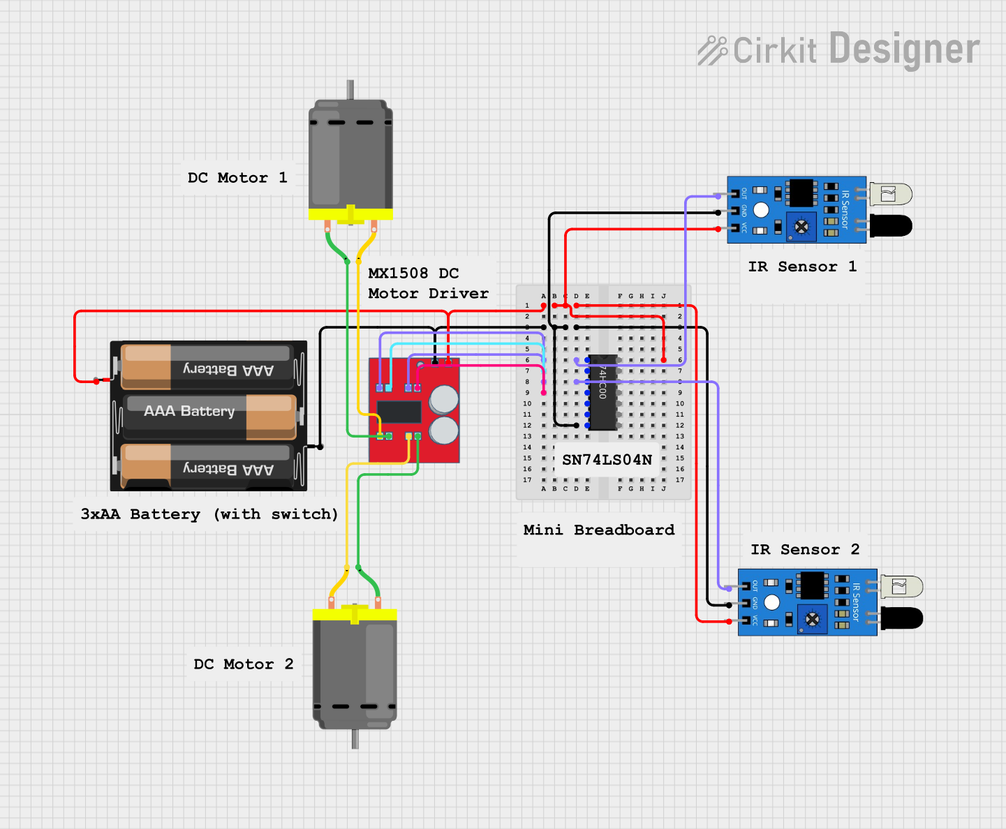

Explore Projects Built with Quadruple Half-H Drivers
Common Applications
- Robotics (e.g., controlling wheels or robotic arms)
- DC motor control for industrial and hobbyist projects
- Stepper motor driving
- Relay and solenoid control
- Automation systems
Technical Specifications
The L293D is a robust and versatile IC with the following key specifications:
| Parameter | Value |
|---|---|
| Supply Voltage (Vcc1) | 4.5V to 36V |
| Logic Voltage (Vcc2) | 4.5V to 7V |
| Output Current (per channel) | 600mA (continuous) |
| Peak Output Current | 1.2A |
| Power Dissipation | 5W (maximum) |
| Operating Temperature Range | -40°C to 150°C |
| Input Logic Levels | Low: 0V to 1.5V, High: 2.3V to 7V |
| Output Voltage Drop | 1.4V (typical) |
Pin Configuration and Descriptions
The L293D is a 16-pin IC with the following pinout:
| Pin Number | Pin Name | Description |
|---|---|---|
| 1 | Enable 1,2 | Enables output for channels 1 and 2 (active high) |
| 2 | Input 1 | Logic input for channel 1 |
| 3 | Output 1 | Output for channel 1 |
| 4 | GND | Ground (common for logic and motor supply) |
| 5 | GND | Ground (common for logic and motor supply) |
| 6 | Output 2 | Output for channel 2 |
| 7 | Input 2 | Logic input for channel 2 |
| 8 | Vcc2 (Motor) | Motor supply voltage (4.5V to 36V) |
| 9 | Enable 3,4 | Enables output for channels 3 and 4 (active high) |
| 10 | Input 3 | Logic input for channel 3 |
| 11 | Output 3 | Output for channel 3 |
| 12 | GND | Ground (common for logic and motor supply) |
| 13 | GND | Ground (common for logic and motor supply) |
| 14 | Output 4 | Output for channel 4 |
| 15 | Input 4 | Logic input for channel 4 |
| 16 | Vcc1 (Logic) | Logic supply voltage (4.5V to 7V) |
Usage Instructions
How to Use the L293D in a Circuit
- Power Supply: Connect the motor supply voltage (Vcc2) to pin 8 and the logic supply voltage (Vcc1) to pin 16. Ensure that the supply voltages are within the specified range.
- Ground Connections: Connect all ground pins (4, 5, 12, and 13) to the common ground of the circuit.
- Enable Pins: Set the enable pins (1 and 9) high to activate the corresponding channels.
- Logic Inputs: Use the input pins (2, 7, 10, and 15) to control the direction of the motor. A high signal on an input pin drives the corresponding output high.
- Outputs: Connect the motor terminals to the output pins (3, 6, 11, and 14). The outputs will drive the motor based on the logic inputs.
Example Circuit with Arduino UNO
Below is an example of how to control a DC motor using the L293D and an Arduino UNO:
Circuit Connections
- Connect Vcc1 (pin 16) to the Arduino's 5V pin.
- Connect Vcc2 (pin 8) to an external power supply (e.g., 12V for the motor).
- Connect all ground pins (4, 5, 12, 13) to the Arduino's GND.
- Connect Enable 1,2 (pin 1) to Arduino pin 9.
- Connect Input 1 (pin 2) to Arduino pin 8.
- Connect Input 2 (pin 7) to Arduino pin 7.
- Connect the motor terminals to Output 1 (pin 3) and Output 2 (pin 6).
Arduino Code
// Define L293D pins connected to Arduino
const int enablePin = 9; // Enable pin for channels 1 and 2
const int input1 = 8;    // Input 1 for channel 1
const int input2 = 7;    // Input 2 for channel 2

void setup() {
  // Set pin modes
  pinMode(enablePin, OUTPUT);
  pinMode(input1, OUTPUT);
  pinMode(input2, OUTPUT);

  // Enable the motor driver
  digitalWrite(enablePin, HIGH);
}

void loop() {
  // Rotate motor in one direction
  digitalWrite(input1, HIGH); // Set Input 1 high
  digitalWrite(input2, LOW);  // Set Input 2 low
  delay(2000);                // Run motor for 2 seconds

  // Stop the motor
  digitalWrite(input1, LOW);  // Set Input 1 low
  digitalWrite(input2, LOW);  // Set Input 2 low
  delay(1000);                // Wait for 1 second

  // Rotate motor in the opposite direction
  digitalWrite(input1, LOW);  // Set Input 1 low
  digitalWrite(input2, HIGH); // Set Input 2 high
  delay(2000);                // Run motor for 2 seconds

  // Stop the motor
  digitalWrite(input1, LOW);  // Set Input 1 low
  digitalWrite(input2, LOW);  // Set Input 2 low
  delay(1000);                // Wait for 1 second
}
Important Considerations
- Ensure that the motor supply voltage (Vcc2) matches the voltage rating of the motor.
- Use appropriate decoupling capacitors between Vcc1, Vcc2, and ground to reduce noise.
- Avoid exceeding the maximum current rating of 600mA per channel to prevent damage to the IC.
- Use a heat sink if the IC becomes excessively hot during operation.
Troubleshooting and FAQs
Common Issues
Motor Not Running:
- Check if the enable pins are set high.
- Verify the logic inputs and ensure they are correctly configured.
- Ensure the motor supply voltage (Vcc2) is connected and within range.
Overheating:
- Ensure the current drawn by the motor does not exceed 600mA per channel.
- Use a heat sink or improve ventilation around the IC.
Erratic Motor Behavior:
- Check for loose connections in the circuit.
- Add decoupling capacitors to reduce electrical noise.
FAQs
Q: Can the L293D drive stepper motors?
A: Yes, the L293D can drive stepper motors by controlling the sequence of logic inputs. Each pair of half-H drivers can control one coil of the stepper motor.
Q: What is the difference between Vcc1 and Vcc2?
A: Vcc1 powers the logic circuitry of the IC (4.5V to 7V), while Vcc2 powers the motors or inductive loads (4.5V to 36V).
Q: Can I use the L293D with a 3.3V microcontroller?
A: The L293D requires a minimum logic voltage of 4.5V. You may need a level shifter to interface it with a 3.3V microcontroller.
Q: How many motors can the L293D control?
A: The L293D can control up to two DC motors or one stepper motor.