Cirkit Designer Logo
Cirkit Designer
Your all-in-one circuit design IDE
Home / 
Component Documentation

How to Use Adafruit 0.56 inch 7-segment LED Backpack Red: Examples, Pinouts, and Specs

Image of Adafruit 0.56 inch 7-segment LED Backpack Red
Cirkit Designer LogoDesign with Adafruit 0.56 inch 7-segment LED Backpack Red in Cirkit Designer

Introduction

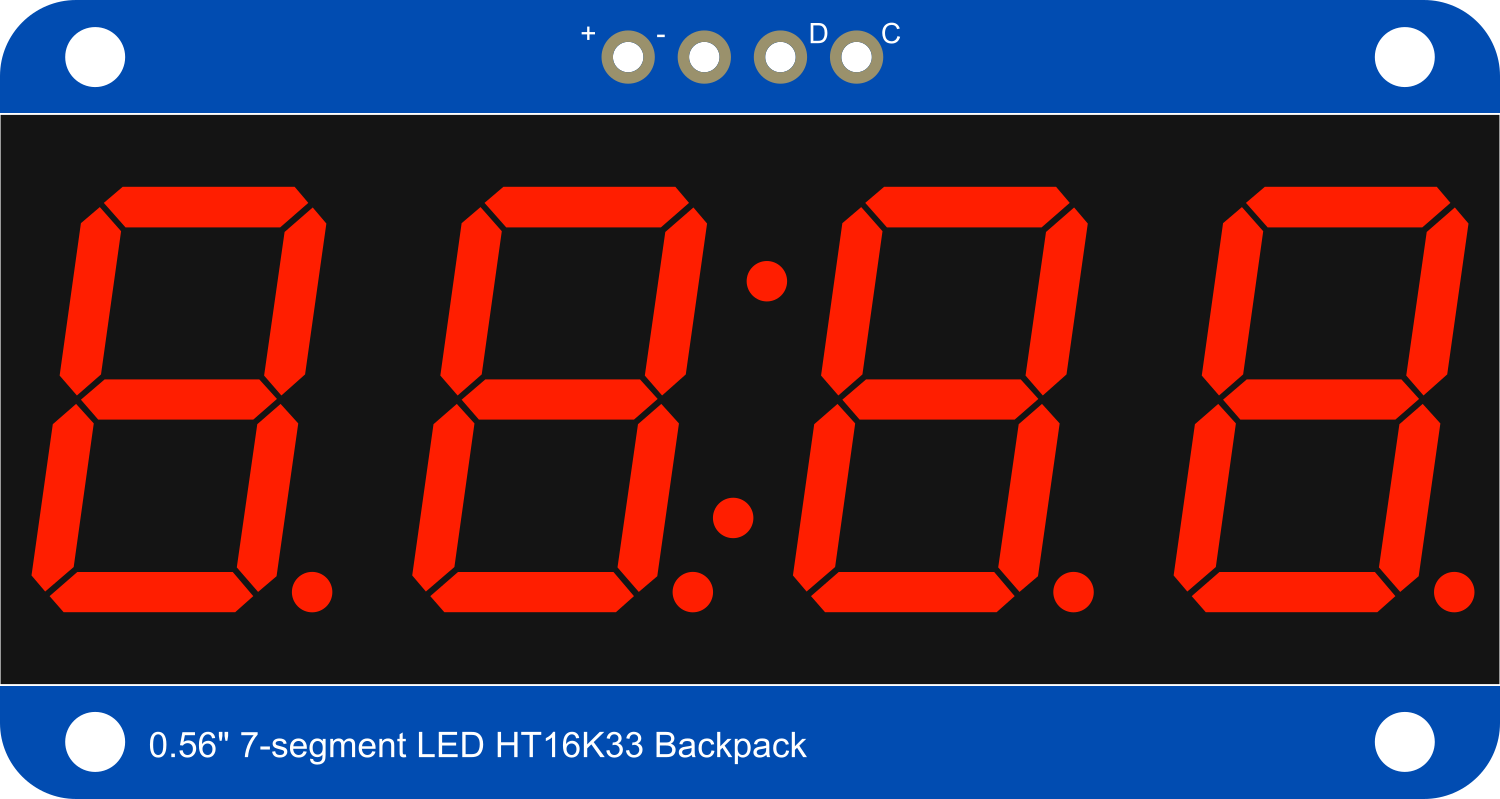
The Adafruit 0.56 inch 7-segment LED Backpack Red is a user-friendly module designed to drive 7-segment LED displays. This component simplifies the process of displaying numbers and characters with its bright red LEDs. It is ideal for projects requiring numeric output, such as clocks, counters, and readouts in various electronics applications.

Explore Projects Built with Adafruit 0.56 inch 7-segment LED Backpack Red

Use Cirkit Designer to design, explore, and prototype these projects online. Some projects support real-time simulation. Click "Open Project" to start designing instantly!
Arduino UNO Controlled Dual Seven Segment Display with Pushbutton Interaction and AHT10 Temperature Sensor
Image of enel290: A project utilizing Adafruit 0.56 inch 7-segment LED Backpack Red in a practical application
This circuit features an Arduino UNO microcontroller connected to two seven-segment displays, a pushbutton, a red LED with a 330-ohm resistor, and an AHT10 temperature and humidity sensor. The Arduino controls the segments of the displays via its digital pins and reads the pushbutton state. The LED is used as an indicator, and the AHT10 sensor interfaces with the Arduino over I2C to provide environmental data.
Cirkit Designer LogoOpen Project in Cirkit Designer
Battery-Powered Sensor Hub with Adafruit QT Py RP2040 and OLED Display
Image of 512: A project utilizing Adafruit 0.56 inch 7-segment LED Backpack Red in a practical application
This circuit features an Adafruit QT Py RP2040 microcontroller interfacing with an MPU-6050 accelerometer, an Adafruit APDS-9960 sensor, and a 0.96" OLED display via I2C communication. It is powered by a 3.7V LiPo battery and includes a green LED with a current-limiting resistor connected to an analog pin of the microcontroller.
Cirkit Designer LogoOpen Project in Cirkit Designer
Battery-Powered Smart Light with Proximity Sensor and OLED Display using Adafruit QT Py RP2040
Image of lab: A project utilizing Adafruit 0.56 inch 7-segment LED Backpack Red in a practical application
This circuit is a portable, battery-powered system featuring an Adafruit QT Py RP2040 microcontroller that interfaces with an OLED display, a proximity sensor, an accelerometer, and an RGB LED strip. The system is powered by a lithium-ion battery with a step-up boost converter to provide 5V for the LED strip, and it includes a toggle switch for power control. The microcontroller communicates with the sensors and display via I2C.
Cirkit Designer LogoOpen Project in Cirkit Designer
Battery-Powered Arduino UNO Smart Light with NeoPixel and ADXL345
Image of Cubagick: A project utilizing Adafruit 0.56 inch 7-segment LED Backpack Red in a practical application
This circuit is a battery-powered system featuring an Arduino UNO that controls an Adafruit NeoPixel Stick and interfaces with an ADXL345 accelerometer and an ILI9341 TFT display. The TP4056 module charges a 18650 battery, which powers the system through a DC-DC converter. The Arduino code drives the NeoPixel Stick to display a red light sequence.
Cirkit Designer LogoOpen Project in Cirkit Designer

Explore Projects Built with Adafruit 0.56 inch 7-segment LED Backpack Red

Use Cirkit Designer to design, explore, and prototype these projects online. Some projects support real-time simulation. Click "Open Project" to start designing instantly!
Image of enel290: A project utilizing Adafruit 0.56 inch 7-segment LED Backpack Red in a practical application
Arduino UNO Controlled Dual Seven Segment Display with Pushbutton Interaction and AHT10 Temperature Sensor
This circuit features an Arduino UNO microcontroller connected to two seven-segment displays, a pushbutton, a red LED with a 330-ohm resistor, and an AHT10 temperature and humidity sensor. The Arduino controls the segments of the displays via its digital pins and reads the pushbutton state. The LED is used as an indicator, and the AHT10 sensor interfaces with the Arduino over I2C to provide environmental data.
Cirkit Designer LogoOpen Project in Cirkit Designer
Image of 512: A project utilizing Adafruit 0.56 inch 7-segment LED Backpack Red in a practical application
Battery-Powered Sensor Hub with Adafruit QT Py RP2040 and OLED Display
This circuit features an Adafruit QT Py RP2040 microcontroller interfacing with an MPU-6050 accelerometer, an Adafruit APDS-9960 sensor, and a 0.96" OLED display via I2C communication. It is powered by a 3.7V LiPo battery and includes a green LED with a current-limiting resistor connected to an analog pin of the microcontroller.
Cirkit Designer LogoOpen Project in Cirkit Designer
Image of lab: A project utilizing Adafruit 0.56 inch 7-segment LED Backpack Red in a practical application
Battery-Powered Smart Light with Proximity Sensor and OLED Display using Adafruit QT Py RP2040
This circuit is a portable, battery-powered system featuring an Adafruit QT Py RP2040 microcontroller that interfaces with an OLED display, a proximity sensor, an accelerometer, and an RGB LED strip. The system is powered by a lithium-ion battery with a step-up boost converter to provide 5V for the LED strip, and it includes a toggle switch for power control. The microcontroller communicates with the sensors and display via I2C.
Cirkit Designer LogoOpen Project in Cirkit Designer
Image of Cubagick: A project utilizing Adafruit 0.56 inch 7-segment LED Backpack Red in a practical application
Battery-Powered Arduino UNO Smart Light with NeoPixel and ADXL345
This circuit is a battery-powered system featuring an Arduino UNO that controls an Adafruit NeoPixel Stick and interfaces with an ADXL345 accelerometer and an ILI9341 TFT display. The TP4056 module charges a 18650 battery, which powers the system through a DC-DC converter. The Arduino code drives the NeoPixel Stick to display a red light sequence.
Cirkit Designer LogoOpen Project in Cirkit Designer

Common Applications

  • Digital clocks
  • Timers
  • Counters
  • Scoreboards
  • Thermometers

Technical Specifications

Key Technical Details

  • Display Color: Red
  • Digit Height: 0.56 inches
  • Operating Voltage: 2.7V - 5.5V
  • Max Current: 100mA (all LEDs on)
  • Interface: I2C
  • I2C Addresses: 0x70 (default) - 0x77 (selectable with solder jumpers)

Pin Configuration and Descriptions

Pin Description
GND Ground connection
VCC Power supply (2.7V - 5.5V)
SDA I2C Data line
SCL I2C Clock line

Usage Instructions

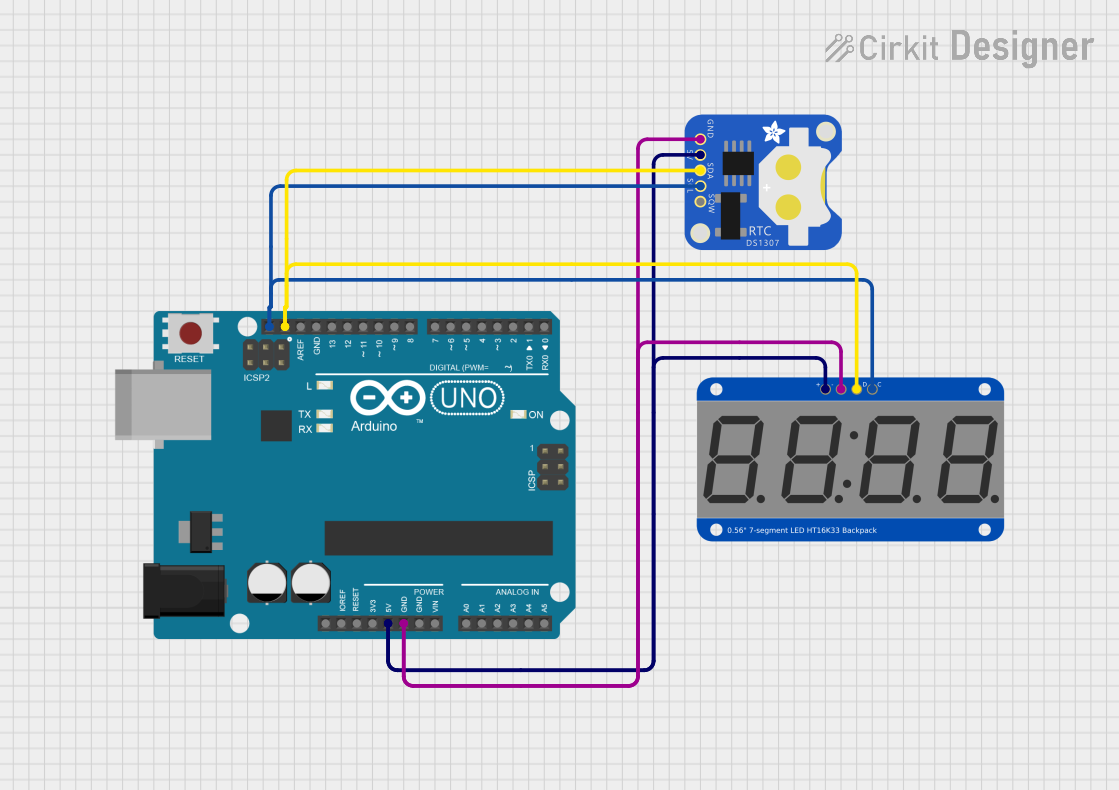
Interfacing with a Circuit

  1. Connect the GND pin to the ground of your power supply.
  2. Connect the VCC pin to a positive power supply (2.7V - 5.5V).
  3. Connect the SDA and SCL pins to the I2C data and clock lines of your microcontroller, respectively.

Important Considerations and Best Practices

  • Ensure that the power supply does not exceed 5.5V to prevent damage.
  • Use pull-up resistors on the I2C lines if your microcontroller does not have built-in pull-ups.
  • To change the I2C address, solder the address jumpers on the back of the PCB.

Example Code for Arduino UNO

#include <Wire.h>
#include <Adafruit_LEDBackpack.h>
#include <Adafruit_GFX.h>

Adafruit_7segment matrix = Adafruit_7segment();

void setup() {
  matrix.begin(0x70); // Initialize the display with its I2C address
}

void loop() {
  matrix.print(1234, DEC); // Display the number 1234
  matrix.writeDisplay();   // Refresh the display with new data
  delay(500);              // Wait for half a second
}

Troubleshooting and FAQs

Common Issues

  • Display not lighting up: Check the power connections and ensure the I2C address is correct.
  • Garbled output: Ensure there are no conflicts with the I2C address and the connections are secure.
  • Dim display: Check if the power supply voltage is too low or if the current limit is too high.

Solutions and Tips

  • Double-check wiring, especially the I2C lines and power supply connections.
  • Use the matrix.setBrightness(uint8_t b) function to adjust the brightness if the display is too dim or too bright.
  • If using multiple displays, make sure each has a unique I2C address.

FAQs

Q: Can I use this module with a 3.3V system? A: Yes, the module can operate at a voltage as low as 2.7V.

Q: How do I change the I2C address? A: Solder the address jumpers on the back of the PCB to configure the address between 0x70 and 0x77.

Q: Can I display letters as well as numbers? A: Yes, the 7-segment display can show some letters and characters, though with limited representation due to the segment layout.

Q: How many of these displays can I chain together? A: You can chain up to 8 displays by setting unique I2C addresses for each.

For further assistance, refer to the Adafruit support forums or the product's FAQ page.