
How to Use 4010 - 12v Fan: Examples, Pinouts, and Specs
 Design with 4010 - 12v Fan in Cirkit Designer
Introduction
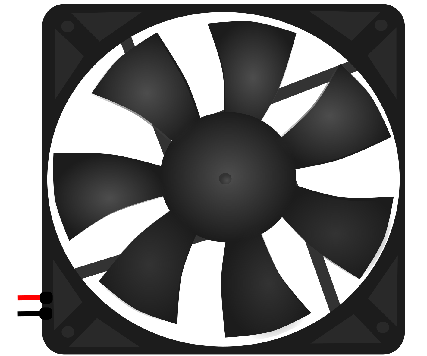
The 4010 - 12V Fan by Nidec is a compact and efficient cooling solution designed for electronic components and systems. With its 40mm x 40mm x 10mm dimensions, this fan is ideal for applications requiring reliable airflow in tight spaces. It operates on a 12V DC power supply and is commonly used in computers, 3D printers, power supplies, and other electronic devices to prevent overheating and ensure optimal performance.
Explore Projects Built with 4010 - 12v Fan
 Open Project in Cirkit Designer
 Open Project in Cirkit Designer
 Open Project in Cirkit Designer
 Open Project in Cirkit Designer
Explore Projects Built with 4010 - 12v Fan
Open Project in Cirkit DesignerOpen Project in Cirkit DesignerOpen Project in Cirkit DesignerOpen Project in Cirkit DesignerCommon Applications
- Cooling CPUs, GPUs, and other heat-generating components in computers
- Ventilation in 3D printers and small enclosures
- Heat dissipation in power supplies and amplifiers
- General-purpose cooling for compact electronic systems
Technical Specifications
Below are the key technical details for the 4010 - 12V Fan:
| Parameter | Specification |
|---|---|
| Manufacturer | Nidec |
| Model | 4010 |
| Dimensions | 40mm x 40mm x 10mm |
| Operating Voltage | 12V DC |
| Operating Current | 0.1A (typical) |
| Power Consumption | 1.2W |
| Airflow | 5.5 CFM (Cubic Feet/Minute) |
| Noise Level | 25 dBA |
| Bearing Type | Sleeve or Ball Bearing |
| Connector Type | 2-pin or 3-pin JST |
| Weight | ~15g |
Pin Configuration
The fan typically comes with a 2-pin or 3-pin connector. Below is the pin configuration:
2-Pin Connector
| Pin | Wire Color | Description |
|---|---|---|
| 1 | Red | Positive (+12V DC) |
| 2 | Black | Ground (GND) |
3-Pin Connector
| Pin | Wire Color | Description |
|---|---|---|
| 1 | Red | Positive (+12V DC) |
| 2 | Black | Ground (GND) |
| 3 | Yellow | Tachometer (Speed Signal) |
Usage Instructions
How to Use the 4010 - 12V Fan in a Circuit
- Power Supply: Ensure the fan is connected to a stable 12V DC power source. Exceeding the voltage rating may damage the fan.
- Wiring:
- For a 2-pin fan, connect the red wire to the positive terminal of the power supply and the black wire to ground.
- For a 3-pin fan, connect the red and black wires as above. The yellow wire can be connected to a microcontroller or monitoring circuit to read the fan's speed.
- Mounting: Secure the fan using screws or adhesive mounts. Ensure the airflow direction aligns with your cooling requirements (airflow direction is typically indicated by arrows on the fan housing).
- Optional Speed Control: Use a PWM (Pulse Width Modulation) signal to control the fan speed if supported by your circuit.
Important Considerations
- Polarity: Always double-check the polarity of the connections to avoid damage.
- Airflow Direction: Verify the airflow direction to ensure proper cooling. The fan typically pulls air from the side with the label and pushes it out the opposite side.
- Noise: If noise is a concern, consider using a fan with a ball bearing for quieter operation.
- Dust Accumulation: Periodically clean the fan to prevent dust buildup, which can reduce efficiency and increase noise.
Example: Connecting to an Arduino UNO
The 4010 - 12V Fan can be controlled using an Arduino UNO and a transistor for switching. Below is an example circuit and code:
Circuit Diagram
- Connect the fan's red wire to the collector of an NPN transistor (e.g., 2N2222).
- Connect the fan's black wire to ground.
- Connect the emitter of the transistor to ground.
- Connect a 1kΩ resistor between the Arduino's PWM pin (e.g., pin 9) and the base of the transistor.
- Connect the fan's power supply (12V) to the red wire through a diode (e.g., 1N4007) for protection.
Arduino Code
// Arduino code to control the speed of a 4010 - 12V Fan using PWM

const int fanPin = 9; // PWM pin connected to the transistor base

void setup() {
  pinMode(fanPin, OUTPUT); // Set the fan pin as an output
}

void loop() {
  // Gradually increase fan speed
  for (int speed = 0; speed <= 255; speed += 5) {
    analogWrite(fanPin, speed); // Write PWM signal to control speed
    delay(50); // Wait 50ms before increasing speed
  }

  // Gradually decrease fan speed
  for (int speed = 255; speed >= 0; speed -= 5) {
    analogWrite(fanPin, speed); // Write PWM signal to control speed
    delay(50); // Wait 50ms before decreasing speed
  }
}
Troubleshooting and FAQs
Common Issues
Fan Not Spinning:
- Check the power supply voltage and ensure it is 12V DC.
- Verify the wiring connections, especially the polarity.
- Inspect the fan for physical obstructions or damage.
Excessive Noise:
- Clean the fan blades to remove dust and debris.
- Ensure the fan is securely mounted to prevent vibrations.
- Consider replacing the fan with a ball-bearing version for quieter operation.
Fan Speed Not Adjustable:
- Ensure the PWM signal is correctly configured if using speed control.
- Verify the transistor and resistor connections in the circuit.
FAQs
Q: Can I use the 4010 - 12V Fan with a 5V power supply?
A: No, the fan is designed to operate at 12V DC. Using a lower voltage may result in insufficient airflow or failure to start.
Q: How do I determine the airflow direction?
A: Look for arrows on the fan housing. One arrow indicates the airflow direction, and the other indicates the blade rotation direction.
Q: Can I connect the fan directly to an Arduino?
A: No, the Arduino cannot supply sufficient current for the fan. Use an external 12V power supply and a transistor for switching.
Q: How do I clean the fan?
A: Use compressed air or a soft brush to remove dust from the blades and housing. Avoid using water or solvents.