
How to Use xlr 3pin male: Examples, Pinouts, and Specs
 Design with xlr 3pin male in Cirkit Designer
Introduction
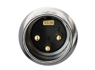
The XLR 3-pin male connector is a widely used component in professional audio, video, and stage lighting applications. It is designed to provide a secure and balanced connection, minimizing noise and interference in signal transmission. The male connector features three pins and is typically used to connect microphones, audio mixers, amplifiers, and other audio equipment to corresponding female XLR sockets.
Explore Projects Built with xlr 3pin male
 Open Project in Cirkit Designer
 Open Project in Cirkit Designer
 Open Project in Cirkit Designer
 Open Project in Cirkit Designer
Explore Projects Built with xlr 3pin male
Open Project in Cirkit DesignerOpen Project in Cirkit DesignerOpen Project in Cirkit DesignerOpen Project in Cirkit DesignerCommon Applications and Use Cases
- Professional audio systems (e.g., microphones, mixers, and amplifiers)
- Stage lighting control systems (DMX512 protocol)
- Audio recording and broadcasting equipment
- Interfacing balanced audio signals in studio and live environments
Technical Specifications
The XLR 3-pin male connector is built to industry standards, ensuring compatibility with a wide range of audio and lighting equipment. Below are the key technical details:
General Specifications
| Parameter | Value |
|---|---|
| Number of Pins | 3 |
| Connector Type | Male |
| Contact Material | Nickel or gold-plated brass |
| Housing Material | Metal (aluminum or zinc alloy) |
| Current Rating | Typically 10 A |
| Voltage Rating | Typically 50 V |
| Operating Temperature | -30°C to +80°C |
| Mounting Style | Cable-mounted or panel-mounted |
Pin Configuration and Descriptions
| Pin Number | Name | Description |
|---|---|---|
| 1 | Ground (GND) | Shield or ground connection for noise reduction |
| 2 | Hot (+) | Positive signal in a balanced audio connection |
| 3 | Cold (-) | Negative signal in a balanced audio connection |
Usage Instructions
How to Use the XLR 3-Pin Male Connector in a Circuit
Wiring the Connector:
- Strip the insulation from the audio cable to expose the three wires: ground, hot, and cold.
- Solder the ground wire to Pin 1, the hot wire to Pin 2, and the cold wire to Pin 3.
- Ensure proper insulation between the pins to prevent short circuits.
Connecting to Equipment:
- Insert the male connector into a compatible female XLR socket.
- Ensure the locking mechanism clicks into place for a secure connection.
Testing the Connection:
- Use a multimeter to verify continuity between the pins and the corresponding wires.
- Test the audio signal to ensure proper transmission without noise or distortion.
Important Considerations and Best Practices
- Always use high-quality cables and connectors to maintain signal integrity.
- Avoid excessive bending or pulling of the cable to prevent damage to the solder joints.
- Ensure the connector is securely locked into the female socket to avoid accidental disconnection.
- For DMX lighting applications, use cables specifically designed for DMX signals to prevent data loss.
Example: Connecting to an Arduino UNO for DMX Lighting
The XLR 3-pin male connector can be used with an Arduino UNO to control DMX lighting systems. Below is an example of how to wire and program the setup:
Wiring Diagram
- Connect Pin 1 (Ground) of the XLR connector to the Arduino GND pin.
- Connect Pin 2 (Hot) of the XLR connector to the Arduino TX (digital pin 1).
- Connect Pin 3 (Cold) to a 120-ohm resistor, then to the Arduino GND pin (for proper termination).
Arduino Code Example
#include <DMXSerial.h> // Include the DMXSerial library for DMX communication

void setup() {
  DMXSerial.init(DMXController); // Initialize as a DMX controller
  DMXSerial.write(1, 255); // Set channel 1 to maximum brightness
}

void loop() {
  // Continuously update DMX values if needed
  DMXSerial.write(1, 128); // Example: Set channel 1 to half brightness
  delay(1000); // Wait for 1 second
  DMXSerial.write(1, 255); // Set channel 1 to full brightness
  delay(1000); // Wait for 1 second
}
Note: Ensure you use a proper RS-485 transceiver module between the Arduino and the XLR connector for DMX communication.
Troubleshooting and FAQs
Common Issues and Solutions
| Issue | Possible Cause | Solution |
|---|---|---|
| No audio signal | Incorrect wiring or loose connection | Verify wiring and ensure secure connections |
| Noise or interference in the signal | Poor shielding or damaged cable | Use high-quality shielded cables |
| Connector does not fit properly | Incompatible connector type | Ensure the connector matches the socket type |
| DMX lighting not responding | Incorrect termination or wiring | Add a 120-ohm termination resistor |
FAQs
Can I use the XLR 3-pin male connector for unbalanced audio?
- Yes, but it is primarily designed for balanced audio. For unbalanced audio, connect Pin 1 (Ground) and Pin 3 (Cold) together.
What is the difference between XLR 3-pin and 5-pin connectors?
- The 3-pin connector is typically used for audio, while the 5-pin connector is used for DMX lighting to support additional data channels.
How do I clean and maintain the connector?
- Use a soft brush or compressed air to remove dust. Avoid using abrasive materials that could damage the contacts.
By following this documentation, you can effectively use the XLR 3-pin male connector in your audio or lighting projects.