
How to Use Servomotor MG995: Examples, Pinouts, and Specs
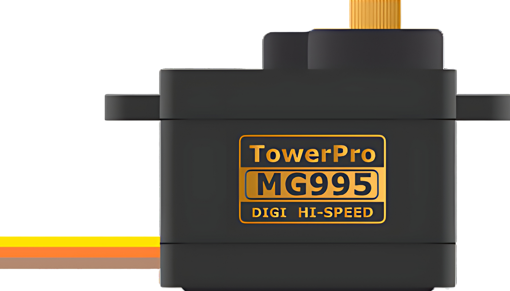
 Design with Servomotor MG995 in Cirkit Designer
Introduction
The MG995 is a high-torque servomotor widely used in the fields of robotics, radio-controlled (RC) models, and industrial automation. It is designed to provide precise control over the angular position of its output shaft, making it an ideal choice for applications requiring accurate movement and positioning. Its robust construction and metal gears make it suitable for high-stress scenarios.
Explore Projects Built with Servomotor MG995
 Open Project in Cirkit Designer
 Open Project in Cirkit Designer
 Open Project in Cirkit Designer
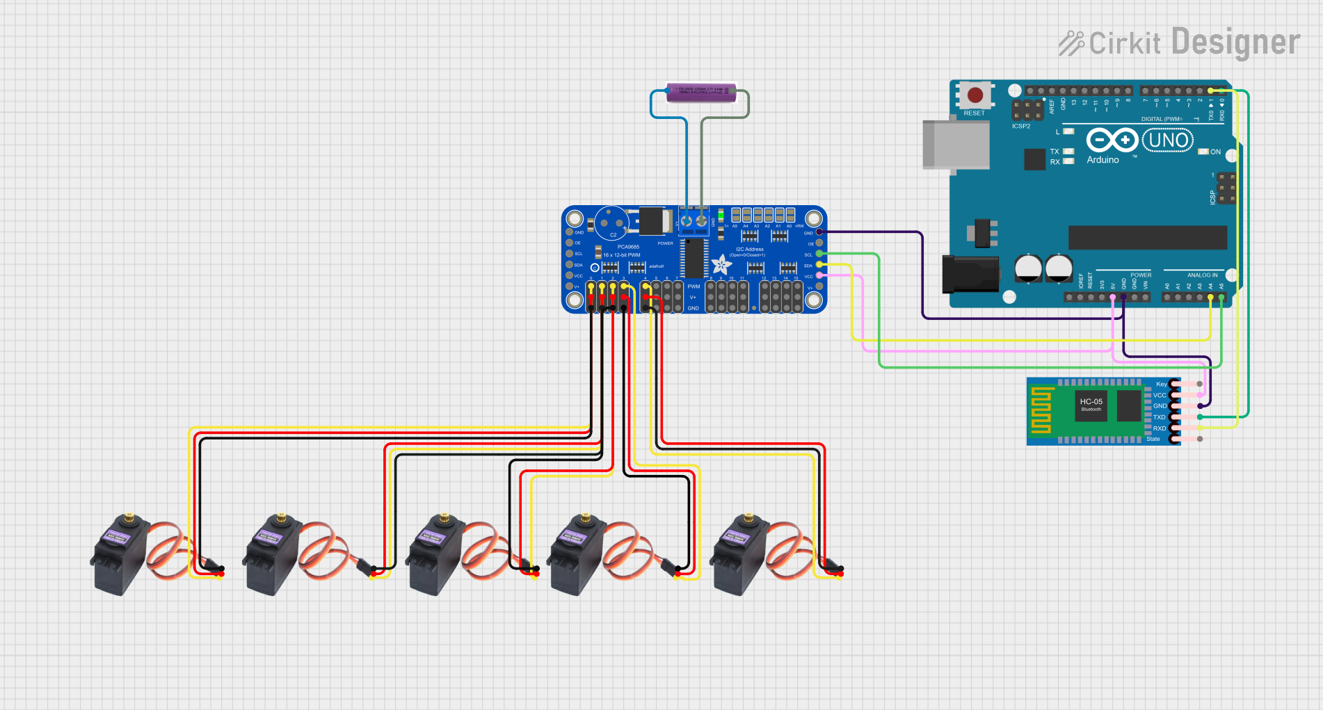
 Open Project in Cirkit Designer
Explore Projects Built with Servomotor MG995

 Open Project in Cirkit Designer
 Open Project in Cirkit Designer
 Open Project in Cirkit Designer
 Open Project in Cirkit Designer
Common Applications and Use Cases
- Robotic arms and manipulators
- Steering mechanisms for RC cars and boats
- Automated doors and windows
- Camera pan/tilt systems
- Animatronics
Technical Specifications
Key Technical Details
- Operating Voltage: 4.8V to 7.2V
- Stall Torque: 9.4 kg-cm (4.8V), 11 kg-cm (6V)
- Operating Speed: 0.19 sec/60° (4.8V), 0.15 sec/60° (6V)
- Temperature Range: -30°C to +60°C
- Weight: 55g
Pin Configuration and Descriptions
| Pin Number | Description | Notes |
|---|---|---|
| 1 | Ground | Connect to system ground |
| 2 | Power Supply (VCC) | 4.8V to 7.2V DC |
| 3 | Control Signal Input | PWM signal, typically 1-2 ms |
Usage Instructions
How to Use the Component in a Circuit
- Power Supply: Connect the power supply pin to a suitable power source within the operating voltage range.
- Ground Connection: Attach the ground pin to the common ground of your system.
- Control Signal: Apply a PWM signal to the control signal input pin to set the desired position of the servo.
Important Considerations and Best Practices
- Ensure that the power supply is capable of delivering sufficient current for the servomotor's operation, especially under load.
- Avoid mechanical blockage or excessive loads that exceed the stall torque rating, as this can damage the motor.
- Use a servo driver or microcontroller with PWM capability to control the MG995.
- Keep the control signal within the recommended pulse width range (1-2 ms) to prevent damage to the servo.
Example Code for Arduino UNO
#include <Servo.h>

Servo myservo;  // Create servo object to control the MG995

void setup() {
  myservo.attach(9);  // Attaches the servo on pin 9 to the servo object
}

void loop() {
  myservo.write(90);  // Set servo to mid-point (90 degrees)
  delay(1000);        // Wait for 1 second
  myservo.write(0);   // Set servo to 0 degrees
  delay(1000);        // Wait for 1 second
  myservo.write(180); // Set servo to 180 degrees
  delay(1000);        // Wait for 1 second
}
Troubleshooting and FAQs
Common Issues Users Might Face
- Servo not responding: Check connections, ensure proper power supply, and verify the PWM signal is within the correct range.
- Jittery movements: This can be due to an insufficient power supply or noise in the control signal. Ensure a stable power source and signal integrity.
- Overheating: Continuous operation at high loads can lead to overheating. Allow the servo to cool down if it becomes too hot.
Solutions and Tips for Troubleshooting
- Power Issues: Use a dedicated power supply for the servomotor, especially when using multiple servos.
- Signal Integrity: Keep the control signal wires away from high-current power wires to minimize interference.
- Mechanical Load: Ensure that the mechanical load does not exceed the servo's rated torque to prevent damage.
FAQs
Q: Can I control the MG995 with a standard RC transmitter and receiver? A: Yes, the MG995 can be controlled using standard RC equipment by connecting it to the receiver's servo channel.
Q: What is the pulse width for the full range of motion? A: The pulse width typically ranges from 1 ms for 0 degrees to 2 ms for 180 degrees, with 1.5 ms representing the 90-degree midpoint.
Q: How can I reverse the direction of rotation? A: To reverse the direction, you can either modify the control signal in software or swap the control signal wires if your controller supports it.