How to Use LD33 Low-Dropout Voltage Regulator: Examples, Pinouts, and Specs
Introduction
The LD33 is a low-dropout (LDO) voltage regulator capable of providing a fixed output voltage of 3.3V with a maximum output current of up to 800mA. This component is ideal for applications requiring a stable 3.3V supply from input voltages that are very close to the output voltage, such as battery-powered devices, microcontroller circuits, and portable electronics.
Explore Projects Built with LD33 Low-Dropout Voltage Regulator

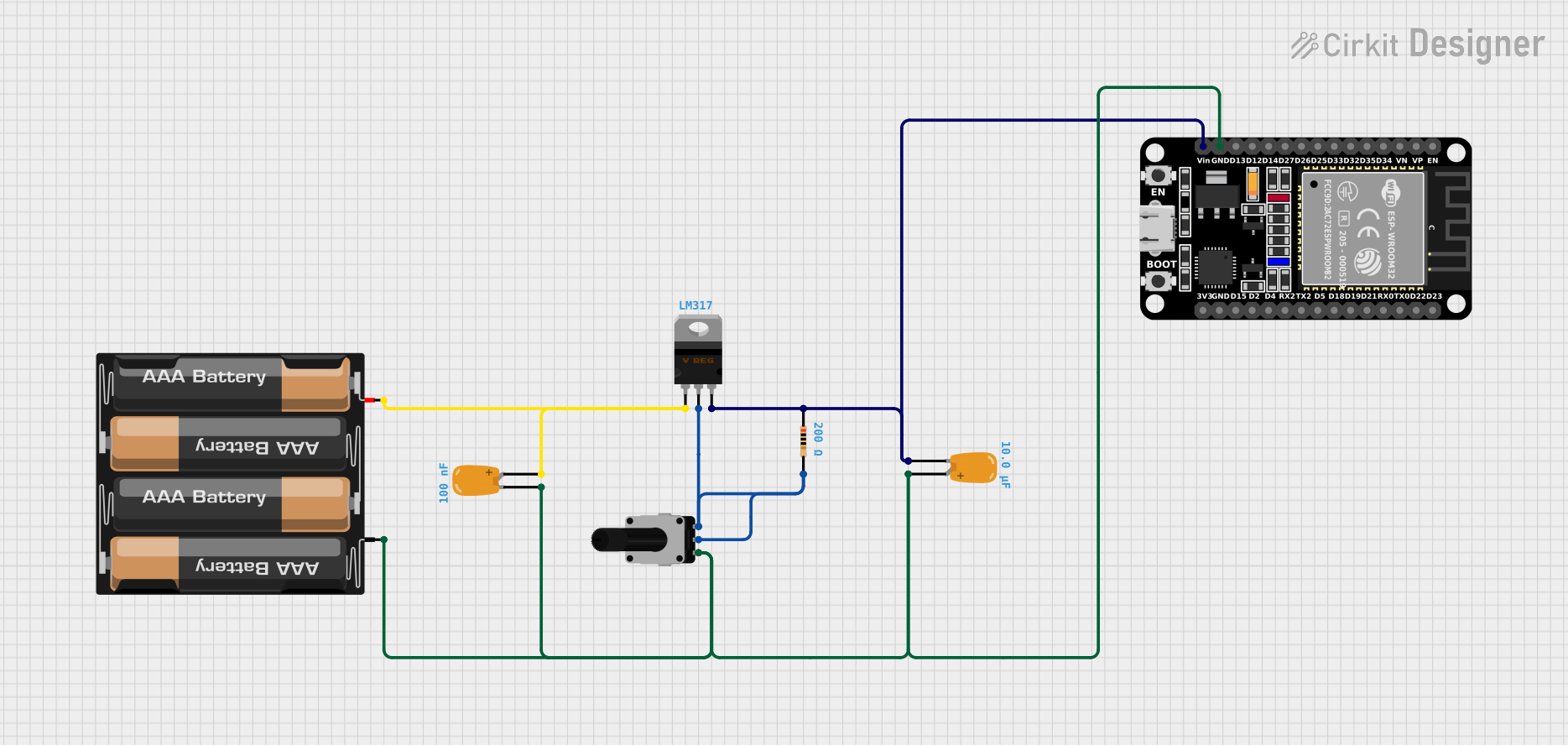


Explore Projects Built with LD33 Low-Dropout Voltage Regulator
Common Applications and Use Cases
- Power supply for 3.3V logic ICs and microcontrollers
- Battery-powered devices requiring a stable 3.3V
- Peripheral power supply for microprocessor systems
- Portable electronics and wearable devices
Technical Specifications
Key Technical Details
- Output Voltage (Vout): 3.3V
- Input Voltage (Vin): 4.5V to 7V (recommended operating range)
- Dropout Voltage: Typically 1V at 800mA load
- Output Current (Iout): Up to 800mA
- Quiescent Current: Typically 5µA
- Temperature Range: -40°C to +125°C
Pin Configuration and Descriptions
| Pin Number | Name | Description |
|---|---|---|
| 1 | IN | Input voltage pin. Connect to the source voltage (4.5V to 7V). |
| 2 | GND | Ground pin. Connect to the system ground. |
| 3 | OUT | Regulated output voltage pin. Provides a stable 3.3V output. |
Usage Instructions
How to Use the LD33 in a Circuit
- Connect the input voltage (4.5V to 7V) to the IN pin of the LD33.
- Connect the GND pin to the system ground.
- The OUT pin will provide a regulated 3.3V output. Connect this to the circuit requiring a 3.3V supply.
- Optionally, add a capacitor (typically 10µF) between the IN pin and GND close to the regulator to stabilize the input supply.
- Similarly, add a capacitor (typically 10µF) between the OUT pin and GND to filter any output noise.
Important Considerations and Best Practices
- Ensure that the input voltage is within the specified range to prevent damage to the LD33.
- Do not exceed the maximum output current of 800mA.
- Use capacitors on the input and output as recommended to minimize voltage fluctuations and noise.
- Provide adequate heat sinking if the regulator is expected to dissipate significant power due to high load current or a large voltage drop from input to output.
Troubleshooting and FAQs
Common Issues
- Output voltage is lower than 3.3V: Check if the input voltage is within the recommended range and if the load current is not exceeding 800mA.
- Regulator is overheating: Ensure that the power dissipation is within the limits and improve heat sinking if necessary.
- Output voltage is unstable: Verify the presence and correct value of the input and output capacitors.
Solutions and Tips for Troubleshooting
- If the output voltage is incorrect, recheck the input voltage and load conditions.
- For overheating issues, reduce the load current or improve heat dissipation.
- For voltage instability, ensure that the recommended capacitors are used and are placed close to the regulator pins.
FAQs
Q: Can I use the LD33 without capacitors? A: While the LD33 may work without capacitors, it is strongly recommended to use them for stability and noise reduction.
Q: What is the maximum input voltage for the LD33? A: The absolute maximum input voltage is typically around 15V, but for safe and reliable operation, keep the input voltage within the recommended range of 4.5V to 7V.
Q: How can I increase the output current capability? A: The LD33 is rated for a maximum of 800mA. If you need more current, consider using a regulator with a higher current rating or parallel multiple LD33 regulators with proper current sharing measures.
Q: Is the LD33 regulator suitable for battery-powered applications? A: Yes, the LD33's low quiescent current makes it suitable for battery-powered applications where power efficiency is crucial.
Example Connection to an Arduino UNO
// No specific code is required for using the LD33 with an Arduino UNO.
// The following example demonstrates how to power an Arduino UNO with the LD33.

// Connect the LD33 as follows:
// LD33 IN pin -> External power supply (4.5V to 7V)
// LD33 GND pin -> External power supply ground and Arduino GND pin
// LD33 OUT pin -> Arduino 3.3V pin

void setup() {
  // Initialize digital pin LED_BUILTIN as an output.
  pinMode(LED_BUILTIN, OUTPUT);
}

void loop() {
  // Turn the LED on (HIGH is the voltage level)
  digitalWrite(LED_BUILTIN, HIGH);
  // Wait for a second
  delay(1000);
  // Turn the LED off by making the voltage LOW
  digitalWrite(LED_BUILTIN, LOW);
   // Wait for a second
  delay(1000);
}
Remember that the Arduino UNO's 3.3V pin is an output, not an input. To power the board with the LD33, connect the LD33's output to a breadboard rail and power the 3.3V components from there, not directly to the Arduino's 3.3V pin.