
How to Use Adafruit I2S MEMS Microphone Breakout - ICS-43434: Examples, Pinouts, and Specs
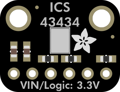
 Design with Adafruit I2S MEMS Microphone Breakout - ICS-43434 in Cirkit Designer
Introduction
The Adafruit I2S MEMS Microphone Breakout - ICS-43434 (Manufacturer Part ID: 6049) is a compact, high-performance digital microphone designed for capturing high-quality audio. It utilizes the I2S (Inter-IC Sound) interface, which allows for easy integration with microcontrollers and single-board computers. The microphone is based on MEMS (Micro-Electro-Mechanical Systems) technology, ensuring a small form factor and reliable performance.
This microphone breakout is ideal for applications such as:
- Voice recognition systems
- Audio recording and processing
- Sound level monitoring
- IoT devices with audio input capabilities
- Embedded systems requiring digital audio capture
Explore Projects Built with Adafruit I2S MEMS Microphone Breakout - ICS-43434
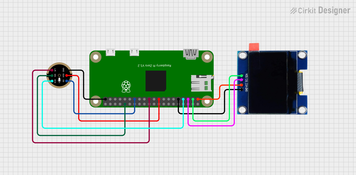 Open Project in Cirkit Designer
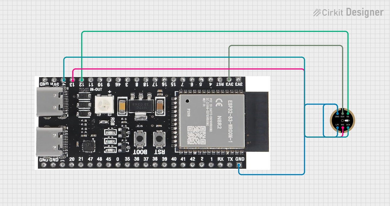 Open Project in Cirkit Designer
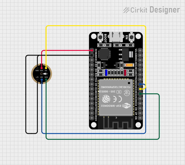 Open Project in Cirkit Designer
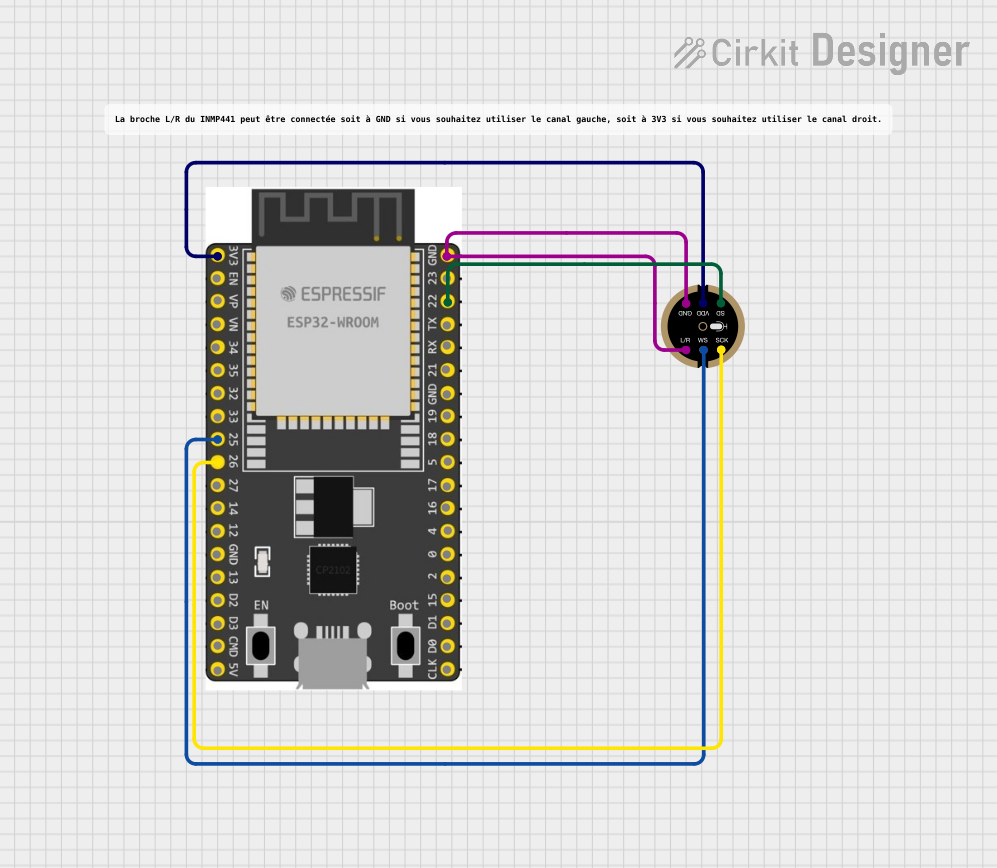 Open Project in Cirkit Designer
Explore Projects Built with Adafruit I2S MEMS Microphone Breakout - ICS-43434
Open Project in Cirkit DesignerOpen Project in Cirkit DesignerOpen Project in Cirkit DesignerOpen Project in Cirkit DesignerTechnical Specifications
Below are the key technical details of the Adafruit I2S MEMS Microphone Breakout:
| Parameter | Value |
|---|---|
| Operating Voltage | 3.3V (recommended) |
| Interface | I2S (Inter-IC Sound) |
| Frequency Response | 50 Hz to 15 kHz |
| Signal-to-Noise Ratio | 64 dB |
| Sensitivity | -26 dBFS |
| Power Consumption | 1.4 mA (typical) |
| Dimensions | 20.5 mm x 17.8 mm x 1.6 mm |
| Operating Temperature | -40°C to +85°C |
Pin Configuration and Descriptions
The breakout board has 7 pins, as described in the table below:
| Pin Name | Description |
|---|---|
| VIN | Power input (3.3V recommended). Can accept up to 5V, but the onboard regulator converts it to 3.3V. |
| GND | Ground connection. |
| BCLK | Bit Clock for I2S communication. |
| LRCLK | Left/Right Clock for I2S communication. |
| DOUT | Digital audio data output. |
| SEL | Channel select pin. Connect to GND for left channel or to VIN for right channel. |
| SD | Shutdown pin. Pull low to disable the microphone and reduce power consumption. |
Usage Instructions
Connecting the Microphone
To use the Adafruit I2S MEMS Microphone Breakout, connect it to a microcontroller or single-board computer that supports I2S communication. Below is a typical connection setup for an Arduino UNO:
| Microphone Pin | Arduino Pin |
|---|---|
| VIN | 3.3V |
| GND | GND |
| BCLK | Pin 3 |
| LRCLK | Pin 2 |
| DOUT | Pin 4 |
| SEL | GND (for left channel) or VIN (for right channel) |
| SD | Leave unconnected or pull high to enable microphone |
Arduino Code Example
The following example demonstrates how to capture audio data from the microphone using an Arduino UNO. This code uses the I2S library, which must be installed in your Arduino IDE.
#include <I2S.h> // Include the I2S library for audio data handling

void setup() {
  Serial.begin(115200); // Initialize serial communication for debugging
  while (!Serial) {
    ; // Wait for the serial port to connect
  }

  // Initialize I2S in receive mode
  if (!I2S.begin(I2S_PHILIPS_MODE, 44100, 32)) {
    Serial.println("Failed to initialize I2S!");
    while (1); // Halt execution if I2S initialization fails
  }

  Serial.println("I2S Microphone Initialized!");
}

void loop() {
  int sample = 0;

  // Check if audio data is available
  if (I2S.available()) {
    sample = I2S.read(); // Read a single audio sample
    Serial.println(sample); // Print the sample value to the serial monitor
  }
}
Important Considerations
- Power Supply: Ensure the microphone is powered with 3.3V for optimal performance. If using a 5V system, the onboard regulator will step down the voltage.
- I2S Pins: Verify that your microcontroller supports I2S communication and configure the pins accordingly.
- Channel Selection: Use the SEL pin to select the audio channel (left or right). Connect SEL to GND for the left channel or to VIN for the right channel.
- Shutdown Pin: Use the SD pin to disable the microphone when not in use to save power.
Troubleshooting and FAQs
Common Issues
No Audio Data Output
- Ensure the microphone is powered correctly (3.3V or 5V to VIN).
- Verify the I2S pins are connected to the correct microcontroller pins.
- Check that the I2S library is properly installed and initialized in your code.
Distorted or Noisy Audio
- Ensure the SEL pin is correctly configured for the desired audio channel.
- Verify that the microphone is not exposed to excessive vibrations or noise sources.
- Check the bit clock (BCLK) and left/right clock (LRCLK) frequencies to ensure they match the microphone's specifications.
Microphone Not Responding
- Confirm that the SD pin is pulled high or left unconnected. Pulling it low disables the microphone.
- Double-check all wiring connections for loose or incorrect connections.
FAQs
Q: Can I use this microphone with a Raspberry Pi?
A: Yes, the Adafruit I2S MEMS Microphone Breakout is compatible with the Raspberry Pi. You can use the I2S interface on the Raspberry Pi to capture audio data. Ensure you configure the I2S pins and software settings correctly.
Q: What is the maximum sampling rate supported?
A: The microphone supports sampling rates up to 48 kHz, but 44.1 kHz is commonly used for most applications.
Q: Can I use this microphone for stereo audio?
A: Yes, you can use two microphones for stereo audio. Configure one microphone for the left channel (SEL to GND) and the other for the right channel (SEL to VIN).
Q: Is this microphone suitable for outdoor use?
A: While the microphone operates in a wide temperature range (-40°C to +85°C), it is not waterproof or weatherproof. Additional protection is required for outdoor use.
By following this documentation, you can effectively integrate the Adafruit I2S MEMS Microphone Breakout into your projects for high-quality audio capture.