
How to Use BUTTON-CONDUCTIVE: Examples, Pinouts, and Specs
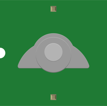
 Design with BUTTON-CONDUCTIVE in Cirkit Designer
Introduction
The BUTTON-CONDUCTIVE is a simple yet essential electronic component designed to complete a circuit when pressed. It allows current to flow through the circuit, triggering an action such as turning on an LED, activating a buzzer, or sending a signal to a microcontroller. This component is widely used in various applications, including user interfaces, control panels, and embedded systems.
Explore Projects Built with BUTTON-CONDUCTIVE
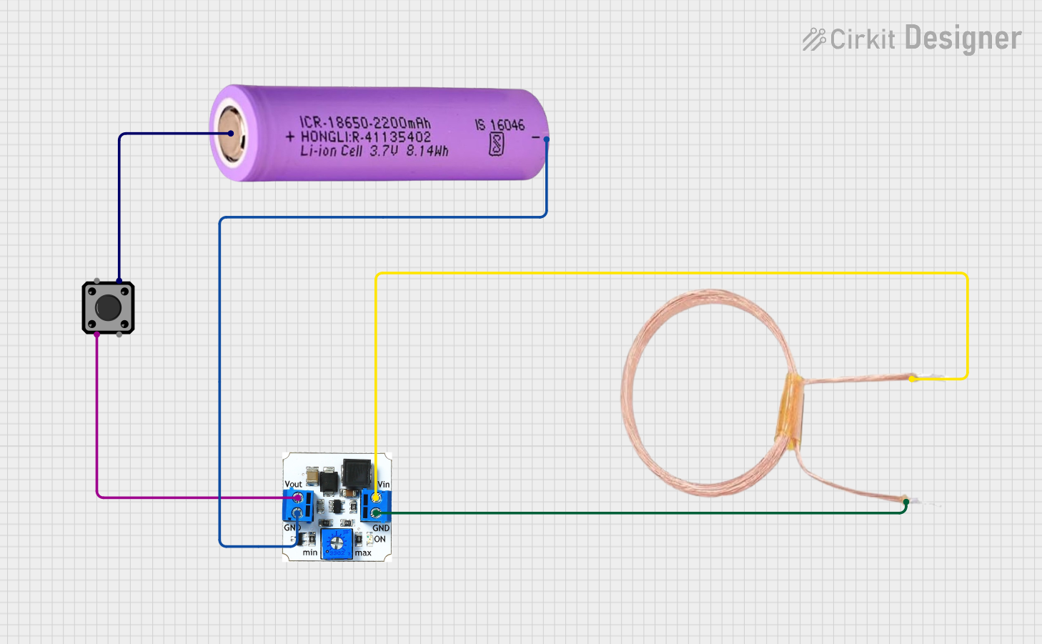 Open Project in Cirkit Designer
 Open Project in Cirkit Designer
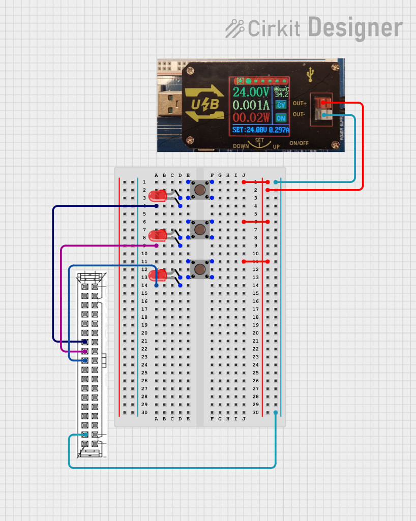 Open Project in Cirkit Designer
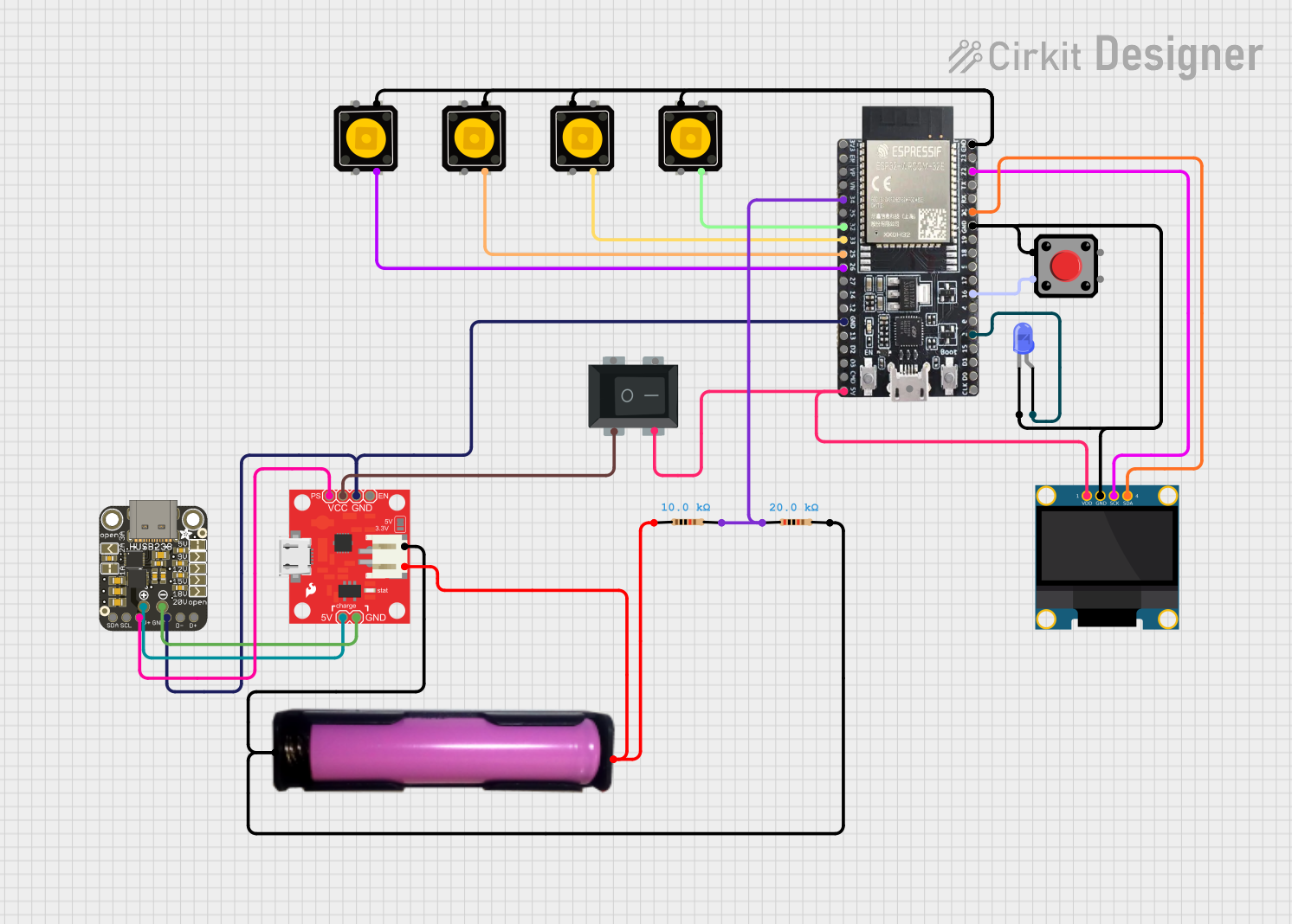 Open Project in Cirkit Designer
Explore Projects Built with BUTTON-CONDUCTIVE
Open Project in Cirkit DesignerOpen Project in Cirkit DesignerOpen Project in Cirkit DesignerOpen Project in Cirkit DesignerCommon Applications and Use Cases
- User Input Devices: Keyboards, remote controls, and game controllers.
- Control Systems: Start/stop buttons in machinery or appliances.
- Prototyping: Triggering actions in Arduino or Raspberry Pi projects.
- Educational Projects: Teaching basic circuit concepts and logic.
Technical Specifications
The BUTTON-CONDUCTIVE is a momentary push-button switch that operates by completing a circuit when pressed. Below are its key specifications:
| Parameter | Value |
|---|---|
| Operating Voltage | 3.3V to 12V |
| Maximum Current Rating | 50mA |
| Contact Resistance | ≤ 100 mΩ |
| Insulation Resistance | ≥ 100 MΩ |
| Operating Temperature | -20°C to +70°C |
| Actuation Force | 160 ± 50 gf |
| Lifespan | 100,000 cycles |
Pin Configuration and Descriptions
The BUTTON-CONDUCTIVE typically has two or four pins, depending on the model. Below is the pin configuration for a standard four-pin button:
| Pin Number | Description |
|---|---|
| 1 | Terminal 1 (connect to circuit) |
| 2 | Terminal 2 (connect to circuit) |
| 3 | Terminal 1 (internally connected) |
| 4 | Terminal 2 (internally connected) |
Note: Pins 1 and 3 are internally connected, as are pins 2 and 4. This allows for flexibility in wiring.
Usage Instructions
How to Use the BUTTON-CONDUCTIVE in a Circuit
- Identify the Pins: For a four-pin button, identify the two pairs of internally connected pins (e.g., 1-3 and 2-4).
- Connect to Circuit:
- Connect one pair of pins (e.g., 1 and 3) to the positive side of the circuit.
- Connect the other pair (e.g., 2 and 4) to the input or load (e.g., an LED or microcontroller pin).
- Add a Pull-Down Resistor: To ensure proper operation, connect a pull-down resistor (e.g., 10kΩ) between the input pin and ground. This prevents floating signals when the button is not pressed.
- Test the Circuit: Press the button to complete the circuit and observe the desired action.
Important Considerations and Best Practices
- Debouncing: Mechanical buttons can produce noise or "bouncing" when pressed. Use a capacitor or software debouncing to filter out unwanted signals.
- Current Limiting: Ensure the current through the button does not exceed its maximum rating (50mA). Use a resistor if necessary.
- Mounting: Secure the button properly to avoid accidental disconnections or damage during use.
Example: Connecting to an Arduino UNO
Below is an example of how to use the BUTTON-CONDUCTIVE with an Arduino UNO to toggle an LED:
// Define pin numbers
const int buttonPin = 2;  // Button connected to digital pin 2
const int ledPin = 13;    // LED connected to digital pin 13

// Variable to store button state
int buttonState = 0;

void setup() {
  pinMode(buttonPin, INPUT);  // Set button pin as input
  pinMode(ledPin, OUTPUT);   // Set LED pin as output
}

void loop() {
  // Read the state of the button
  buttonState = digitalRead(buttonPin);

  // If button is pressed, turn on the LED
  if (buttonState == HIGH) {
    digitalWrite(ledPin, HIGH);  // Turn LED on
  } else {
    digitalWrite(ledPin, LOW);   // Turn LED off
  }
}
Note: Use a pull-down resistor (10kΩ) between the button pin and ground to ensure stable operation.
Troubleshooting and FAQs
Common Issues and Solutions
Button Not Responding
- Cause: Incorrect wiring or loose connections.
- Solution: Double-check the pin connections and ensure the button is securely mounted.
LED Stays On or Off
- Cause: Missing pull-down resistor or incorrect resistor value.
- Solution: Add a 10kΩ pull-down resistor between the button pin and ground.
Unstable or Flickering Output
- Cause: Button bouncing or noise.
- Solution: Implement software debouncing in your code or add a small capacitor (e.g., 0.1µF) across the button terminals.
Button Feels Stiff or Unresponsive
- Cause: Physical damage or wear.
- Solution: Replace the button if it has exceeded its lifespan or is physically damaged.
FAQs
Q1: Can I use the BUTTON-CONDUCTIVE with a 5V power supply?
A1: Yes, the BUTTON-CONDUCTIVE operates within a voltage range of 3.3V to 12V, so 5V is suitable.
Q2: How do I debounce the button in software?
A2: You can use a delay or a state-checking algorithm in your code to filter out bouncing signals. For example, wait 50ms after detecting a button press before reading the state again.
Q3: Can I use the BUTTON-CONDUCTIVE in high-current applications?
A3: No, the BUTTON-CONDUCTIVE is rated for a maximum current of 50mA. For higher currents, use a relay or transistor to handle the load.
Q4: What is the lifespan of the BUTTON-CONDUCTIVE?
A4: The button is rated for 100,000 cycles under normal operating conditions.