How to Use mbed lpc 1768: Examples, Pinouts, and Specs
Introduction
The mbed LPC1768 is a microcontroller board built around the NXP LPC1768 chip, which features a 32-bit ARM Cortex-M3 core. It is designed for rapid prototyping and development, making it an excellent choice for engineers, hobbyists, and students. The board provides built-in USB support, Ethernet connectivity, and a wide range of I/O options, enabling it to handle diverse embedded applications. Its compact design and compatibility with the mbed online development environment make it a versatile and user-friendly platform.
Explore Projects Built with mbed lpc 1768
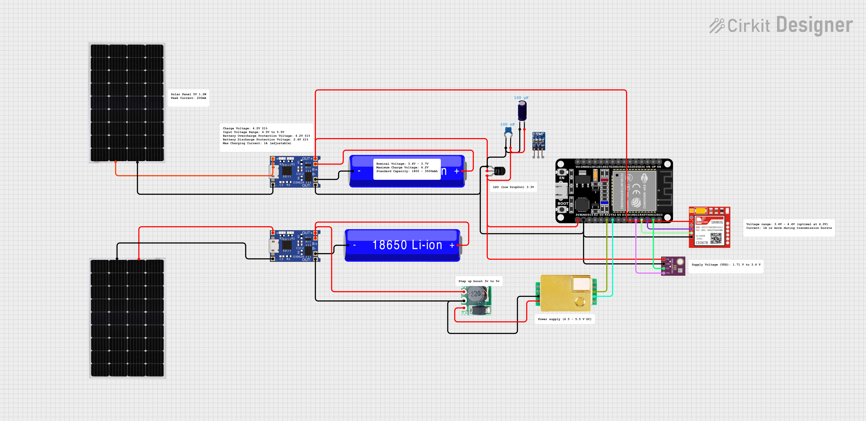
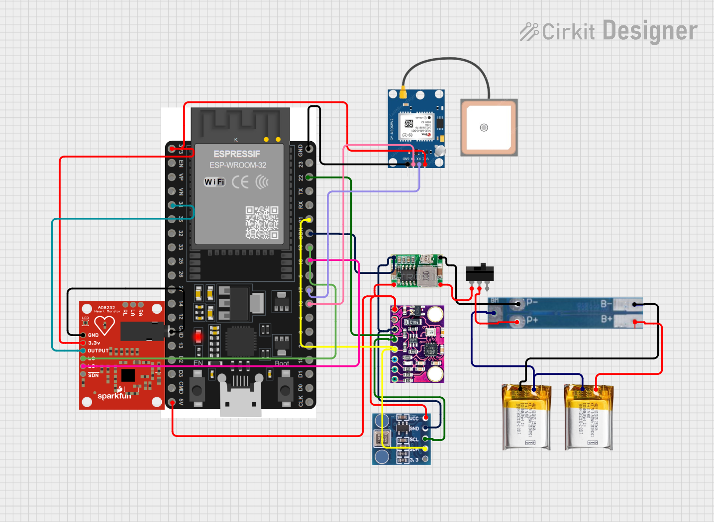
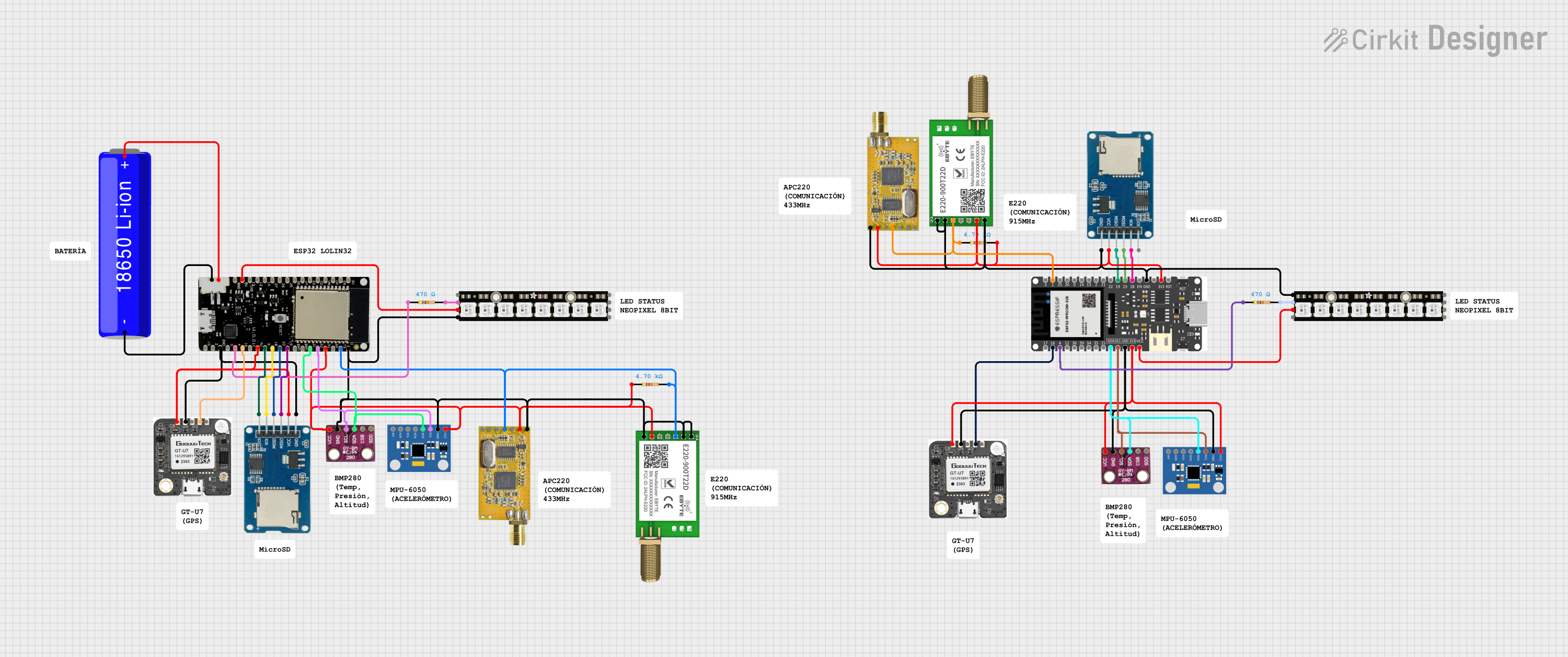

Explore Projects Built with mbed lpc 1768
Common Applications and Use Cases
- IoT (Internet of Things) devices
- Robotics and automation systems
- Data acquisition and processing
- Prototyping for industrial control systems
- Educational projects and research
Technical Specifications
The mbed LPC1768 offers a robust set of features and specifications, making it suitable for a variety of applications.
Key Technical Details
- Microcontroller: NXP LPC1768 (ARM Cortex-M3, 32-bit)
- Clock Speed: 96 MHz
- Flash Memory: 512 KB
- RAM: 64 KB
- Digital I/O Pins: 40
- Analog Input Pins: 6 (12-bit ADC)
- Analog Output Pins: 1 (10-bit DAC)
- Communication Interfaces: UART, SPI, I2C, CAN, Ethernet
- Power Supply: 4.5V to 9V (via VIN) or 5V (via USB)
- USB Support: USB 2.0 (Full Speed)
- Dimensions: 54 mm x 26 mm
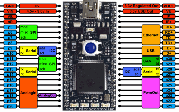
Pin Configuration and Descriptions
The mbed LPC1768 has a 40-pin DIP form factor. Below is a summary of the pin configuration:
| Pin | Name | Description |
|---|---|---|
| 1 | VOUT | 3.3V output |
| 2 | GND | Ground |
| 3 | p5 | Digital I/O or ADC input (AIN0) |
| 4 | p6 | Digital I/O or ADC input (AIN1) |
| 5 | p7 | Digital I/O or ADC input (AIN2) |
| 6 | p8 | Digital I/O or ADC input (AIN3) |
| 7 | p9 | Digital I/O or ADC input (AIN4) |
| 8 | p10 | Digital I/O or ADC input (AIN5) |
| 9 | p11 | Digital I/O or UART TX |
| 10 | p12 | Digital I/O or UART RX |
| ... | ... | ... |
| 39 | VIN | Power input (4.5V to 9V) |
| 40 | USB | USB power and communication |
For a complete pinout diagram, refer to the official mbed LPC1768 datasheet.
Usage Instructions
How to Use the mbed LPC1768 in a Circuit
Powering the Board:
- Connect the board to a computer via a USB cable for power and programming.
- Alternatively, supply 4.5V to 9V to the VIN pin for standalone operation.
Programming the Board:
- Use the mbed online compiler (https://os.mbed.com/compiler/) to write and compile your code.
- Drag and drop the compiled binary file onto the mbed LPC1768, which appears as a USB mass storage device.
Connecting Peripherals:
- Use the digital and analog pins to interface with sensors, actuators, and other devices.
- Utilize communication interfaces (UART, SPI, I2C) for advanced peripherals.
Important Considerations and Best Practices
- Ensure the power supply voltage does not exceed the specified range to avoid damaging the board.
- Use pull-up or pull-down resistors for unused input pins to prevent floating states.
- Avoid drawing excessive current from the 3.3V VOUT pin, as it is limited to 70 mA.
- When using Ethernet, ensure proper grounding and shielding to minimize noise.
Example Code for Arduino-Compatible Usage
The mbed LPC1768 can be programmed using the mbed online compiler. Below is an example of blinking an LED connected to pin p21:
#include "mbed.h"

// Define an LED object connected to pin p21
DigitalOut led(p21);

int main() {
    while (true) {
        led = 1;  // Turn the LED on
        wait(0.5); // Wait for 500 ms
        led = 0;  // Turn the LED off
        wait(0.5); // Wait for 500 ms
    }
}
Notes:
- Replace
p21with the pin number where your LED is connected. - The
wait()function introduces a delay in seconds.
Troubleshooting and FAQs
Common Issues and Solutions
The board is not recognized by the computer:
- Ensure the USB cable is functional and supports data transfer.
- Check if the board is properly powered.
- Try connecting to a different USB port or computer.
Code does not run after uploading:
- Verify that the binary file was successfully copied to the board.
- Ensure the code is compiled for the correct target (mbed LPC1768).
- Check for errors in the code, such as incorrect pin assignments.
Ethernet connection is not working:
- Confirm that the Ethernet cable is securely connected.
- Verify the network configuration in your code (e.g., IP address, subnet mask).
- Test the network connection with a different device.
Analog readings are inaccurate:
- Ensure the input voltage does not exceed the ADC reference voltage (3.3V).
- Use proper grounding and shielding to reduce noise.
FAQs
Can I use the mbed LPC1768 with Arduino IDE?
No, the mbed LPC1768 is not directly compatible with the Arduino IDE. Use the mbed online compiler or other ARM-compatible development tools.What is the maximum current output of the GPIO pins?
Each GPIO pin can source or sink up to 4 mA. For higher currents, use external drivers.Can I power the board with a LiPo battery?
Yes, as long as the voltage is within the 4.5V to 9V range. Use a voltage regulator if necessary.Is the mbed LPC1768 suitable for low-power applications?
Yes, the ARM Cortex-M3 core supports low-power modes, but additional optimization may be required in your code.
This concludes the documentation for the mbed LPC1768. For further details, refer to the official mbed documentation and datasheets.