How to Use NXP current sensor: Examples, Pinouts, and Specs
Introduction
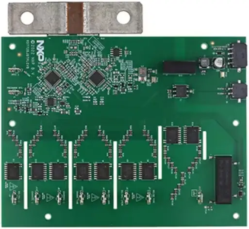
The NXP Current Sensor (Part ID: Uno) is a precision device designed to measure the current flowing through a circuit. It provides accurate and real-time feedback, making it ideal for monitoring and control applications. This sensor is widely used in power management systems, motor control, battery monitoring, and industrial automation. Its robust design and high accuracy make it suitable for both low-current and high-current applications.
Explore Projects Built with NXP current sensor

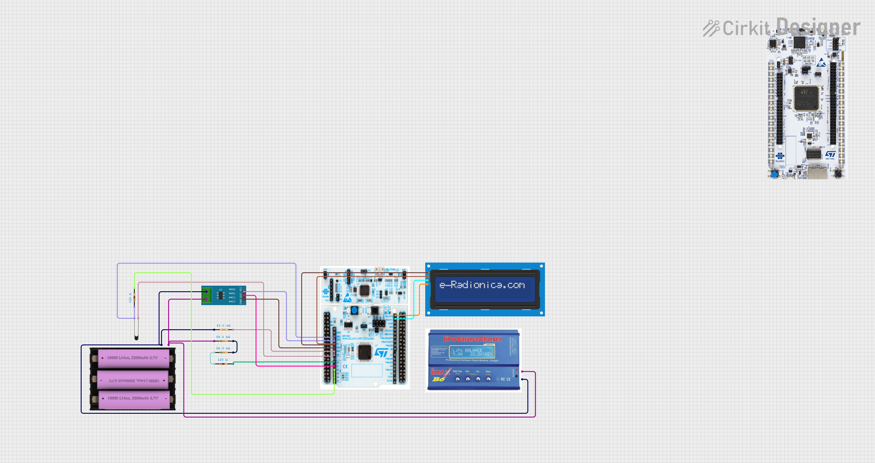
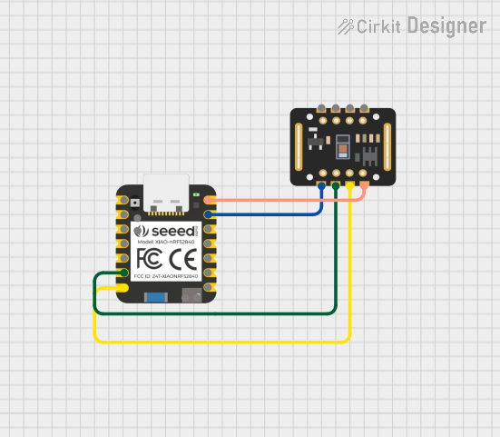
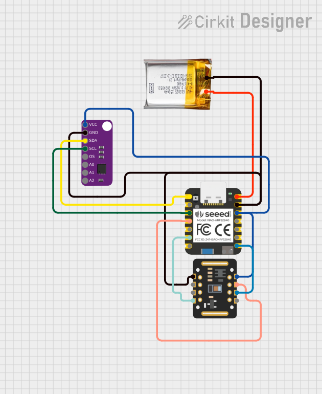
Explore Projects Built with NXP current sensor
Technical Specifications
The following table outlines the key technical specifications of the NXP Current Sensor (Uno):
| Parameter | Value |
|---|---|
| Supply Voltage (Vcc) | 3.3V to 5V |
| Current Measurement Range | ±30A |
| Output Signal Type | Analog Voltage |
| Sensitivity | 66mV/A (typical) |
| Accuracy | ±1% |
| Operating Temperature | -40°C to +125°C |
| Response Time | < 5 µs |
| Package Type | SOIC-8 |
Pin Configuration and Descriptions
The NXP Current Sensor (Uno) has an 8-pin configuration. The table below describes each pin:
| Pin Number | Pin Name | Description |
|---|---|---|
| 1 | Vcc | Power supply input (3.3V to 5V). |
| 2 | GND | Ground connection. |
| 3 | OUT | Analog output signal proportional to the current. |
| 4 | NC | No connection (leave unconnected). |
| 5 | NC | No connection (leave unconnected). |
| 6 | NC | No connection (leave unconnected). |
| 7 | NC | No connection (leave unconnected). |
| 8 | NC | No connection (leave unconnected). |
Usage Instructions
How to Use the Component in a Circuit
- Power the Sensor: Connect the
Vccpin to a 3.3V or 5V power supply and theGNDpin to the ground of your circuit. - Connect the Current Path: Place the sensor in series with the load whose current you want to measure. Ensure the current flows through the sensor in the correct direction as indicated in the datasheet.
- Read the Output: The
OUTpin provides an analog voltage proportional to the current flowing through the sensor. This output can be read using an ADC (Analog-to-Digital Converter) on a microcontroller.
Important Considerations and Best Practices
- Bypass Capacitor: Place a 0.1 µF ceramic capacitor between
VccandGNDto filter out noise. - Current Range: Ensure the current flowing through the sensor does not exceed the specified range (±30A) to avoid damage or inaccurate readings.
- Temperature Effects: The sensor is temperature-compensated, but extreme temperatures may still slightly affect accuracy.
- PCB Layout: Minimize the trace resistance in the current path to reduce power loss and improve measurement accuracy.
Example: Connecting to an Arduino UNO
The NXP Current Sensor (Uno) can be easily interfaced with an Arduino UNO to measure current. Below is an example circuit and code:
Circuit Connections
- Connect
Vccto the 5V pin on the Arduino. - Connect
GNDto the GND pin on the Arduino. - Connect the
OUTpin to an analog input pin (e.g., A0) on the Arduino.
Arduino Code
// NXP Current Sensor (Uno) Example Code
// This code reads the analog output of the sensor and calculates the current.

const int sensorPin = A0; // Analog pin connected to the sensor's OUT pin
const float sensitivity = 0.066; // Sensor sensitivity in V/A (66mV/A)
const float vcc = 5.0; // Arduino supply voltage (5V)
const int adcResolution = 1024; // 10-bit ADC resolution

void setup() {
  Serial.begin(9600); // Initialize serial communication
  pinMode(sensorPin, INPUT); // Set the sensor pin as input
}

void loop() {
  int sensorValue = analogRead(sensorPin); // Read the analog value
  float voltage = (sensorValue * vcc) / adcResolution; // Convert to voltage
  float current = voltage / sensitivity; // Calculate current in Amperes

  // Print the current value to the Serial Monitor
  Serial.print("Current: ");
  Serial.print(current, 2); // Print current with 2 decimal places
  Serial.println(" A");

  delay(1000); // Wait for 1 second before the next reading
}
Troubleshooting and FAQs
Common Issues and Solutions
No Output Signal:
- Cause: Incorrect power supply or loose connections.
- Solution: Verify that
Vccis connected to a 3.3V or 5V source and that all connections are secure.
Inaccurate Readings:
- Cause: Noise or incorrect calibration.
- Solution: Add a bypass capacitor (0.1 µF) between
VccandGND. Ensure the sensitivity value in your calculations matches the sensor's datasheet.
Output Voltage Saturation:
- Cause: Current exceeds the sensor's range.
- Solution: Ensure the current flowing through the sensor is within the specified range (±30A).
Temperature Drift:
- Cause: Operating in extreme temperatures.
- Solution: Use the sensor within the recommended temperature range (-40°C to +125°C).
FAQs
Q1: Can this sensor measure both AC and DC currents?
A1: Yes, the NXP Current Sensor (Uno) can measure both AC and DC currents.
Q2: What is the maximum resolution of the sensor?
A2: The resolution depends on the ADC used. For example, with a 10-bit ADC and a 5V reference, the resolution is approximately 4.88 mV per step.
Q3: Can I use this sensor with a 3.3V microcontroller?
A3: Yes, the sensor operates with a supply voltage of 3.3V to 5V, making it compatible with 3.3V microcontrollers.
Q4: Is the sensor isolated from the current path?
A4: No, this sensor is not isolated. For isolation, consider using a Hall-effect-based current sensor.
Q5: How do I calibrate the sensor?
A5: To calibrate, measure the output voltage with no current flowing through the sensor. This is your zero-current offset. Subtract this value from subsequent readings to improve accuracy.