How to Use Gearmotor DC Wheels left: Examples, Pinouts, and Specs
Introduction
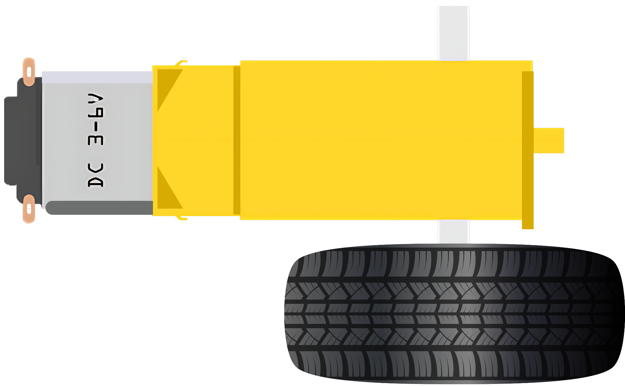
A Gearmotor DC Wheels Left is a specialized motor designed for use in robotics and vehicular applications. It combines a direct current (DC) electric motor with a gearbox to enhance torque while reducing speed, tailored specifically for driving the left-side wheels of a vehicle. This integration allows for precise control over the movement and speed of the vehicle, making it an essential component in the construction of robots, electric vehicles, and automated systems.
Explore Projects Built with Gearmotor DC Wheels left

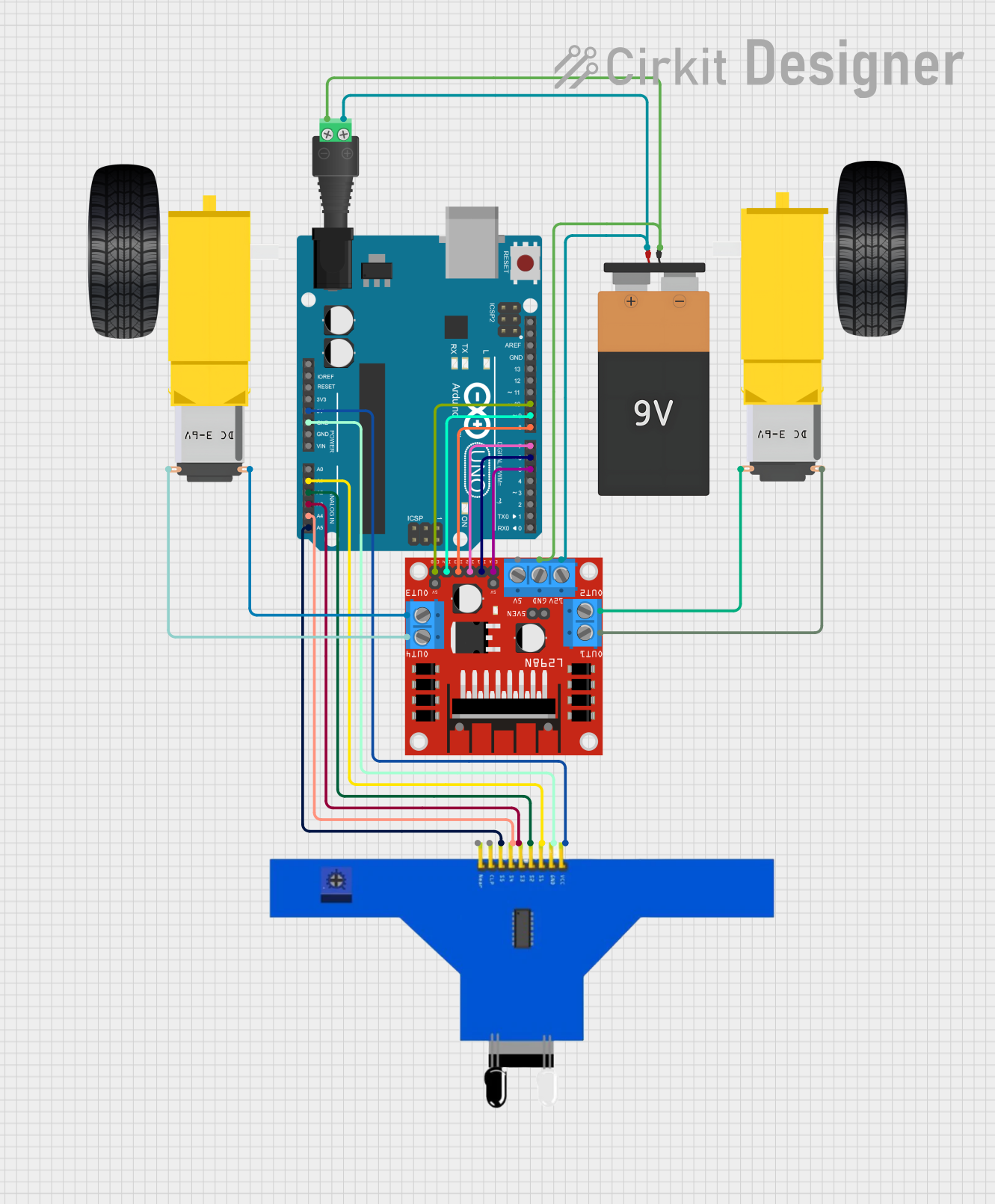
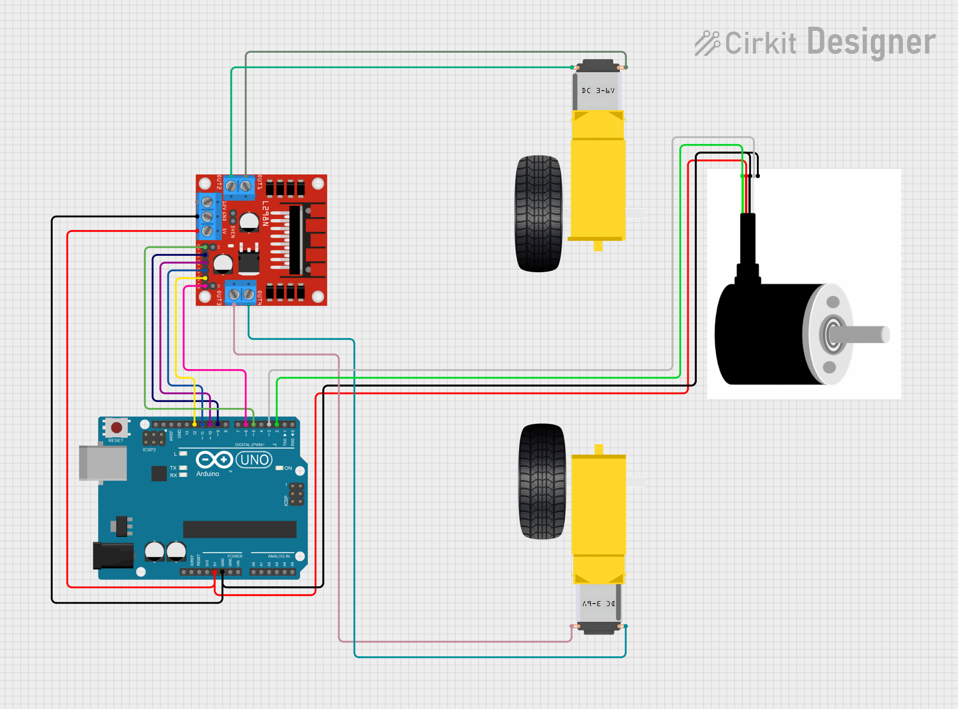
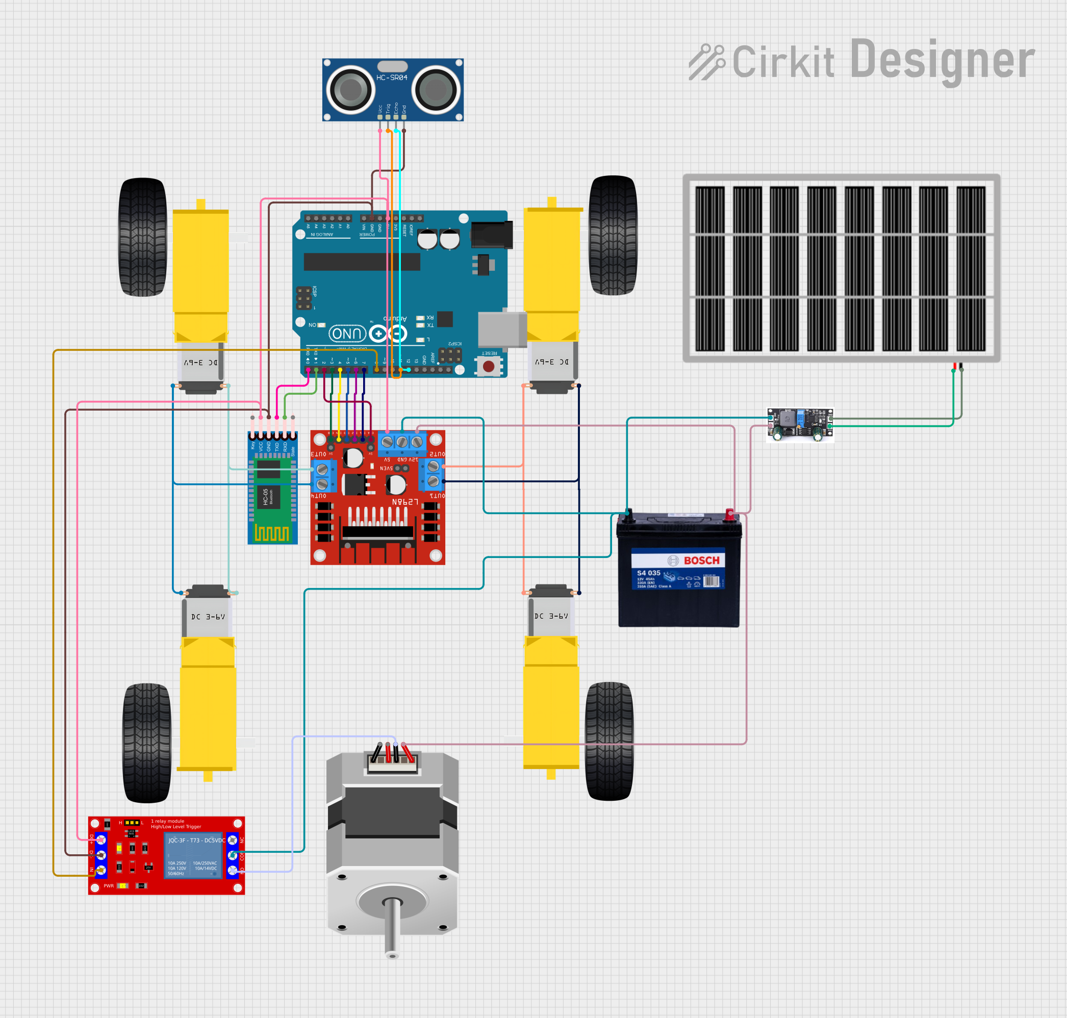
Explore Projects Built with Gearmotor DC Wheels left
Common Applications and Use Cases
- Robotics: Used in the drive systems of robots to control left-side movement.
- Electric Vehicles: Installed in electric cars or scooters to power the left wheels.
- Automated Guided Vehicles (AGVs): Essential for the directional movement in warehouses and industrial settings.
- Hobby Projects: Ideal for DIY projects involving remote-controlled cars or similar vehicles.
Technical Specifications
Key Technical Details
- Voltage Range: Typically 3V to 12V DC
- No-Load Current: Varies based on model and load
- Stall Current: Varies based on model and load
- Torque: Varies based on gear ratio and motor characteristics
- Speed: Varies based on gear ratio and voltage applied
- Direction: Designed to rotate in a direction optimal for left-side wheel movement
Pin Configuration and Descriptions
| Pin Number | Description | Notes |
|---|---|---|
| 1 | Motor Positive (+) | Connect to positive voltage |
| 2 | Motor Negative (−) | Connect to ground |
Usage Instructions
How to Use the Component in a Circuit
- Power Connection: Connect the motor positive and negative pins to your power source, ensuring that the voltage matches the motor's specifications.
- Control: To control the motor's speed and direction, use a motor driver that can handle the motor's current requirements.
- Mounting: Secure the gearmotor to your vehicle or project, ensuring that the wheel is aligned correctly for left-side movement.
Important Considerations and Best Practices
- Voltage Matching: Always use a power supply that matches the voltage rating of the motor to prevent damage.
- Current Handling: Ensure that all control electronics can handle the stall current of the motor.
- Heat Dissipation: Provide adequate cooling if the motor is expected to run near its maximum load for extended periods.
- Electrical Noise: Use capacitors across the motor terminals to minimize electrical noise and potential interference with other electronics.
Troubleshooting and FAQs
Common Issues Users Might Face
- Motor Not Running: Check power supply connections and verify that the voltage is within the specified range.
- Insufficient Torque: Ensure that the gear ratio is suitable for the load. Consider using a motor with higher torque specifications if necessary.
- Overheating: Reduce the load on the motor or improve cooling.
Solutions and Tips for Troubleshooting
- Intermittent Operation: Check for loose connections and solder joints.
- Noise Issues: Add capacitors across the motor terminals to filter out noise.
- Directional Problems: Verify that the motor is mounted correctly for left-side operation.
Example Code for Arduino UNO
// Example code to control a Gearmotor DC Wheels Left with an Arduino UNO
#include <Arduino.h>

const int motorPin1 = 3; // Motor control pin 1
const int motorPin2 = 4; // Motor control pin 2

void setup() {
  pinMode(motorPin1, OUTPUT);
  pinMode(motorPin2, OUTPUT);
}

void loop() {
  // Rotate the motor in one direction
  digitalWrite(motorPin1, HIGH);
  digitalWrite(motorPin2, LOW);
  delay(1000); // Run for 1 second

  // Stop the motor
  digitalWrite(motorPin1, LOW);
  digitalWrite(motorPin2, LOW);
  delay(1000); // Stop for 1 second

  // Rotate the motor in the opposite direction
  digitalWrite(motorPin1, LOW);
  digitalWrite(motorPin2, HIGH);
  delay(1000); // Run for 1 second

  // Stop the motor
  digitalWrite(motorPin1, LOW);
  digitalWrite(motorPin2, LOW);
  delay(1000); // Stop for 1 second
}
Note: This example assumes the use of a simple motor driver to control the gearmotor. The motor driver's input pins are connected to the Arduino's digital pins 3 and 4. Adjust the pin assignments and control logic to match your specific motor driver and application requirements.