How to Use Blue 16x2 Character Slim OLED Module: Examples, Pinouts, and Specs
Introduction
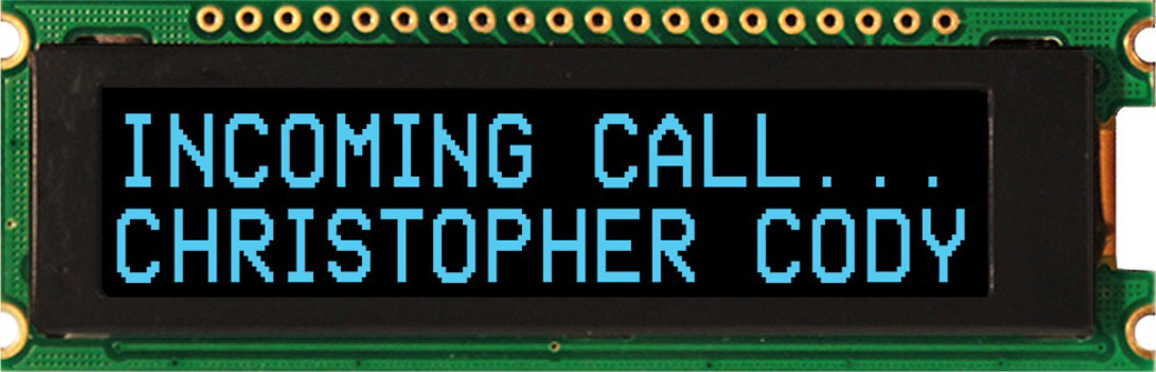
The Blue 16x2 Character Slim OLED Module (Manufacturer Part ID: NHD-0216CW-AB3) by Newhaven Display is a compact and efficient display module designed for embedded systems. It features a 16x2 character layout, utilizing OLED technology to deliver high contrast, wide viewing angles, and low power consumption. This module is ideal for applications requiring clear text display in a compact form factor, such as industrial control panels, consumer electronics, and IoT devices.
Explore Projects Built with Blue 16x2 Character Slim OLED Module


Explore Projects Built with Blue 16x2 Character Slim OLED Module
Common Applications
- Embedded systems and microcontroller projects
- Industrial control panels
- Consumer electronics (e.g., home appliances)
- IoT devices and smart home systems
- Portable devices requiring low-power displays
Technical Specifications
Below are the key technical details and pin configuration for the NHD-0216CW-AB3 module:
Key Technical Details
| Parameter | Specification |
|---|---|
| Display Type | OLED (Organic Light Emitting Diode) |
| Character Layout | 16x2 (16 characters per row, 2 rows) |
| Display Color | Blue characters on a black background |
| Interface | I²C or SPI |
| Operating Voltage | 3.3V |
| Operating Temperature | -40°C to +80°C |
| Dimensions (L x W x H) | 80.0mm x 36.0mm x 10.0mm |
| Viewing Angle | >160° |
| Power Consumption | Low (OLED technology) |
Pin Configuration
The module has a 14-pin interface. The pin configuration is as follows:
| Pin No. | Pin Name | Description |
|---|---|---|
| 1 | GND | Ground |
| 2 | VCC | Power supply (3.3V) |
| 3 | SCL | Serial Clock Line (I²C) |
| 4 | SDA | Serial Data Line (I²C) |
| 5 | RES | Reset (Active Low) |
| 6 | DC | Data/Command Control |
| 7 | CS | Chip Select (Active Low, SPI mode only) |
| 8 | NC | Not Connected |
| 9-14 | Reserved | Reserved for future use |
Usage Instructions
How to Use the Component in a Circuit
- Power Supply: Connect the VCC pin to a 3.3V power source and the GND pin to ground.
- Interface Selection: The module supports both I²C and SPI communication. For I²C:
- Connect the SCL pin to the microcontroller's clock line.
- Connect the SDA pin to the microcontroller's data line.
- Leave the CS pin unconnected.
- Reset: Connect the RES pin to a GPIO pin on the microcontroller for resetting the display.
- Data/Command Control: Use the DC pin to toggle between data and command modes.
- Pull-Up Resistors: For I²C communication, ensure pull-up resistors (typically 4.7kΩ) are connected to the SCL and SDA lines.
Important Considerations and Best Practices
- Voltage Levels: Ensure the module operates at 3.3V. Using 5V may damage the display.
- Initialization: Properly initialize the display using the manufacturer's recommended sequence.
- Viewing Angle: The OLED display offers a wide viewing angle, but ensure it is mounted securely for optimal readability.
- ESD Protection: Handle the module with care to avoid electrostatic discharge damage.
Example Code for Arduino UNO
Below is an example of how to interface the NHD-0216CW-AB3 module with an Arduino UNO using the I²C protocol:
#include <Wire.h> // Include the Wire library for I²C communication

#define OLED_I2C_ADDRESS 0x3C // Default I²C address for the display

void setup() {
  Wire.begin(); // Initialize I²C communication
  initializeOLED(); // Call the function to initialize the display
}

void loop() {
  displayText("Hello, World!"); // Display text on the OLED
  delay(2000); // Wait for 2 seconds
  displayText("16x2 OLED Module"); // Update the text
  delay(2000); // Wait for 2 seconds
}

void initializeOLED() {
  Wire.beginTransmission(OLED_I2C_ADDRESS);
  Wire.write(0x00); // Command mode
  // Send initialization commands (refer to the datasheet for details)
  Wire.write(0xAE); // Display OFF
  Wire.write(0xA8); // Set multiplex ratio
  Wire.write(0x1F); // Multiplex ratio value
  Wire.write(0xD3); // Set display offset
  Wire.write(0x00); // Offset value
  Wire.write(0xAF); // Display ON
  Wire.endTransmission();
}

void displayText(const char* text) {
  Wire.beginTransmission(OLED_I2C_ADDRESS);
  Wire.write(0x40); // Data mode
  while (*text) {
    Wire.write(*text++); // Send each character
  }
  Wire.endTransmission();
}
Notes:
- Replace the initialization commands in
initializeOLED()with the exact sequence provided in the datasheet for the NHD-0216CW-AB3. - Ensure the I²C address (
0x3C) matches the module's configuration.
Troubleshooting and FAQs
Common Issues and Solutions
Display Not Turning On:
- Verify the power supply voltage (3.3V) and connections.
- Check the RES pin to ensure the module is not stuck in reset mode.
No Text Displayed:
- Ensure the initialization sequence is correct.
- Verify the I²C address and connections to the SCL and SDA pins.
Flickering or Unstable Display:
- Check for loose connections or poor soldering.
- Ensure proper pull-up resistors are used on the I²C lines.
Incorrect Characters Displayed:
- Verify the data being sent to the display.
- Ensure the microcontroller's logic levels are compatible with the module.
FAQs
Q: Can this module be powered with 5V?
A: No, the module operates at 3.3V. Using 5V may damage the display.
Q: Does the module support custom characters?
A: Yes, the module supports custom characters. Refer to the datasheet for instructions on creating and displaying custom characters.
Q: Can I use this module with SPI instead of I²C?
A: Yes, the module supports SPI communication. Refer to the datasheet for the required pin connections and initialization sequence.
Q: What is the typical lifespan of the OLED display?
A: The OLED display has a typical lifespan of 50,000 hours under normal operating conditions.