How to Use IGBT: Examples, Pinouts, and Specs
Introduction
An Insulated Gate Bipolar Transistor (IGBT) is a semiconductor device that combines the high input impedance of a MOSFET with the high current-carrying capability of a bipolar transistor. This hybrid functionality makes the IGBT an ideal choice for applications requiring efficient switching and control of high power and voltage.
Common applications of IGBTs include:
- Motor drives and inverters
- Power supplies and converters
- Renewable energy systems (e.g., solar inverters, wind turbines)
- Electric vehicles and industrial automation
Explore Projects Built with IGBT


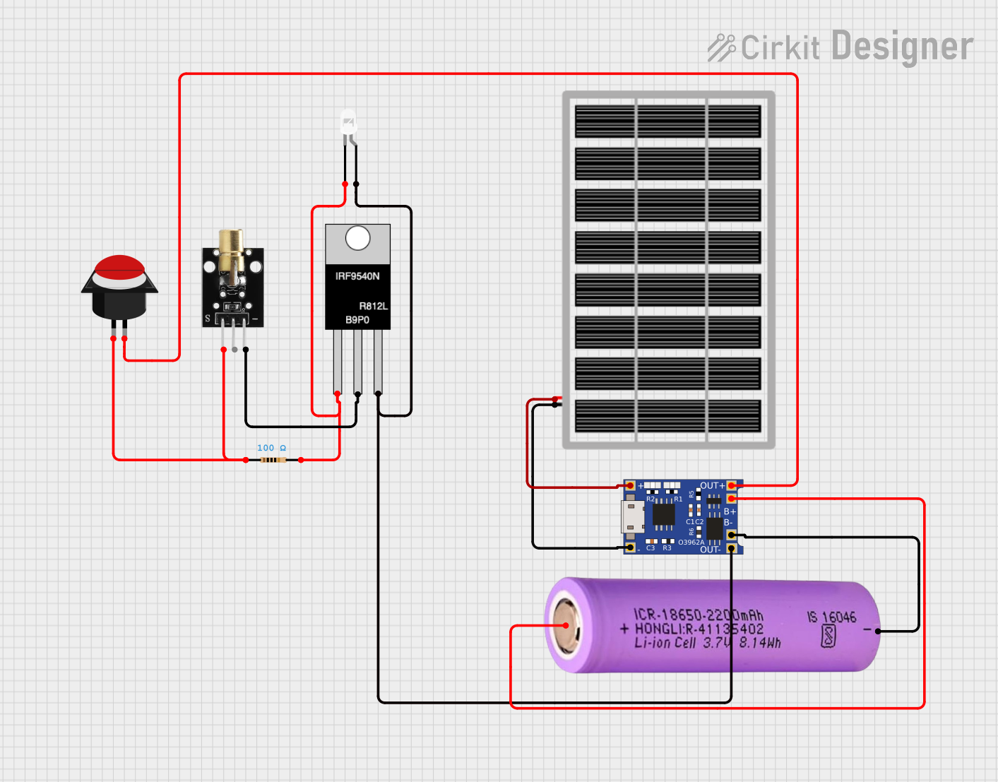

Explore Projects Built with IGBT
Technical Specifications
Below are the key technical specifications of a typical IGBT. Note that actual values may vary depending on the specific model and manufacturer.
| Parameter | Value |
|---|---|
| Voltage Rating (VCE) | 600V to 1200V (common range) |
| Current Rating (IC) | 10A to 100A (depending on model) |
| Gate Threshold Voltage | 4V to 8V |
| Switching Frequency | Up to 50 kHz |
| Power Dissipation | Varies by model (e.g., 50W to 300W) |
| Operating Temperature | -40°C to 150°C |
Pin Configuration and Descriptions
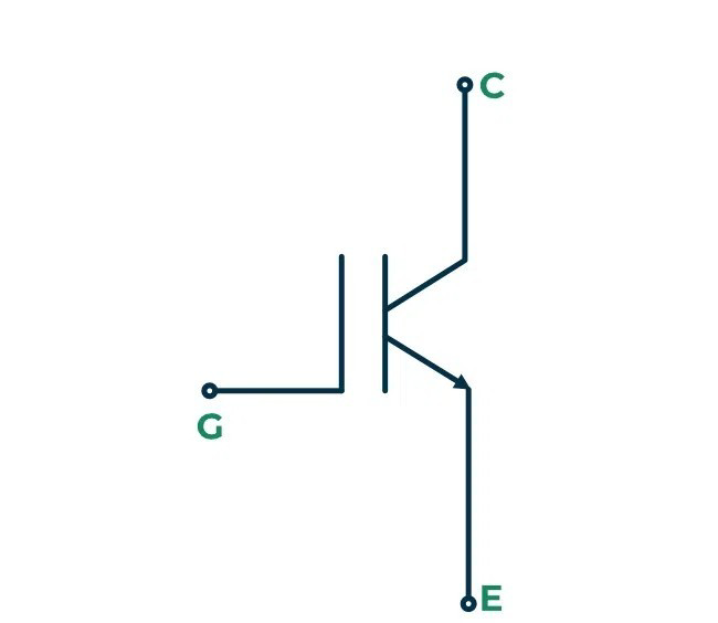
The IGBT typically has three main terminals: Collector, Emitter, and Gate. Below is a description of each pin:
| Pin Name | Description |
|---|---|
| Collector | The terminal through which the main current flows into the IGBT. |
| Emitter | The terminal through which the main current exits the IGBT. |
| Gate | The control terminal used to switch the IGBT on or off by applying a voltage. |
Usage Instructions
How to Use the IGBT in a Circuit
- Gate Drive Circuit: Use a gate driver circuit to control the IGBT. The gate voltage should typically be between 10V and 15V to fully turn on the device. Ensure the gate voltage does not exceed the maximum rating to avoid damage.
- Load Connection: Connect the load between the collector and the positive supply voltage. The emitter is connected to the ground or negative terminal.
- Snubber Circuit: Include a snubber circuit (e.g., an RC network) across the IGBT to protect it from voltage spikes during switching.
- Heat Dissipation: Use a heatsink or cooling mechanism to manage heat dissipation, especially in high-power applications.
Important Considerations and Best Practices
- Switching Speed: Avoid excessive switching speeds to minimize switching losses and electromagnetic interference (EMI).
- Gate Resistor: Use an appropriate gate resistor to limit the inrush current to the gate and control the switching speed.
- Protection: Implement overcurrent and overvoltage protection circuits to safeguard the IGBT.
- Isolation: Ensure proper electrical isolation between the control and power circuits to prevent damage to sensitive components.
Example: Using an IGBT with Arduino UNO
Below is an example of how to control an IGBT using an Arduino UNO to drive a motor.
// Example: Controlling an IGBT with Arduino UNO
// This code demonstrates PWM control of an IGBT to drive a motor.
// Ensure the IGBT is connected to a proper gate driver circuit.

const int pwmPin = 9; // PWM output pin connected to the gate driver

void setup() {
  pinMode(pwmPin, OUTPUT); // Set the PWM pin as an output
}

void loop() {
  analogWrite(pwmPin, 128); // Output 50% duty cycle PWM signal
  delay(2000); // Keep the motor running for 2 seconds

  analogWrite(pwmPin, 0); // Turn off the motor
  delay(2000); // Wait for 2 seconds before restarting
}
Note: Always use a gate driver circuit between the Arduino and the IGBT to ensure proper voltage levels and isolation.
Troubleshooting and FAQs
Common Issues and Solutions
IGBT Overheating
- Cause: Insufficient cooling or excessive current.
- Solution: Use a heatsink or cooling fan. Ensure the current is within the rated limits.
Failure to Switch On
- Cause: Insufficient gate voltage or incorrect gate resistor value.
- Solution: Verify the gate voltage is within the recommended range (10V to 15V). Adjust the gate resistor value if necessary.
Voltage Spikes During Switching
- Cause: Lack of a snubber circuit or improper circuit design.
- Solution: Add a snubber circuit across the IGBT to suppress voltage spikes.
High Switching Losses
- Cause: Excessive switching frequency or improper gate drive.
- Solution: Reduce the switching frequency and optimize the gate drive circuit.
FAQs
Q1: Can I use an IGBT for low-power applications?
A1: While IGBTs are designed for high-power applications, they can be used in low-power circuits. However, MOSFETs are often more efficient for low-power use cases.
Q2: How do I choose the right IGBT for my application?
A2: Consider the voltage and current ratings, switching frequency, and thermal management requirements. Ensure the IGBT's ratings exceed the maximum operating conditions of your circuit.
Q3: What is the difference between an IGBT and a MOSFET?
A3: IGBTs are better suited for high-voltage, high-current applications due to their lower conduction losses. MOSFETs, on the other hand, are faster and more efficient for low-voltage, high-frequency applications.
Q4: Do I need a gate driver for an IGBT?
A4: Yes, a gate driver is essential to provide the required voltage and current to switch the IGBT efficiently and safely.