How to Use TPS63020 2.5V Li-Ion: Examples, Pinouts, and Specs
Introduction
The TPS63020 is a highly efficient DC-DC step-up/step-down converter manufactured by TP. It is specifically designed to provide a regulated output voltage of 2.5V, making it ideal for powering devices from a single Li-Ion battery. This component is capable of operating in both buck (step-down) and boost (step-up) modes, ensuring stable output even when the input voltage fluctuates above or below the desired output voltage.
Explore Projects Built with TPS63020 2.5V Li-Ion


Explore Projects Built with TPS63020 2.5V Li-Ion
Common Applications and Use Cases
- Portable electronics powered by single-cell Li-Ion batteries
- Wearable devices and IoT gadgets
- Battery-powered medical devices
- Industrial sensors and low-power systems
- Applications requiring a stable 2.5V output from variable input voltages
Technical Specifications
The TPS63020 is a versatile and robust power management IC. Below are its key technical details:
Key Specifications
| Parameter | Value |
|---|---|
| Input Voltage Range | 1.8V to 5.5V |
| Output Voltage | 2.5V (fixed) |
| Output Current | Up to 2A |
| Efficiency | Up to 96% |
| Switching Frequency | 2.4 MHz |
| Operating Temperature Range | -40°C to +85°C |
| Package Type | 10-pin VSON (3mm x 3mm) |
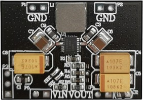
Pin Configuration and Descriptions
The TPS63020 comes in a 10-pin VSON package. Below is the pinout and description:
| Pin Number | Pin Name | Description |
|---|---|---|
| 1 | VIN | Input voltage pin (1.8V to 5.5V). Connect to the power source. |
| 2 | EN | Enable pin. Drive high to enable the converter, low to disable. |
| 3 | PGND | Power ground. Connect to the ground plane of the PCB. |
| 4 | SW | Switch pin. Connect to the inductor. |
| 5 | VOUT | Regulated output voltage (2.5V). Connect to the load. |
| 6 | FB | Feedback pin. Used for output voltage regulation. |
| 7 | AGND | Analog ground. Connect to the ground plane of the PCB. |
| 8 | PS/SYNC | Power save mode or synchronization input. Configure for efficiency or sync. |
| 9 | L1 | Inductor connection pin. |
| 10 | L2 | Inductor connection pin. |
Usage Instructions
The TPS63020 is straightforward to use in a circuit. Below are the steps and considerations for proper implementation:
How to Use the Component in a Circuit
- Power Supply Connection: Connect the input voltage (VIN) pin to a power source within the range of 1.8V to 5.5V. Use a decoupling capacitor (e.g., 10µF) close to the VIN pin to reduce noise.
- Inductor Selection: Choose an inductor with a value between 1µH and 2.2µH, capable of handling the peak current. Connect the inductor between the SW pin and the L1/L2 pins.
- Output Capacitor: Use a low-ESR ceramic capacitor (e.g., 22µF) at the VOUT pin to stabilize the output voltage.
- Enable Pin: Drive the EN pin high to enable the converter. Pull it low to disable the device and reduce power consumption.
- Feedback Resistor: If using an adjustable version of the TPS63020, connect a resistor divider to the FB pin to set the desired output voltage. For the fixed 2.5V version, this pin is internally configured.
- Power Save Mode: Configure the PS/SYNC pin for power save mode (high efficiency at light loads) or synchronization with an external clock.
Important Considerations and Best Practices
- Thermal Management: Ensure proper heat dissipation by using a PCB with a solid ground plane and thermal vias under the IC.
- PCB Layout: Minimize the loop area of the input and output capacitors to reduce EMI. Place components as close to the IC as possible.
- Startup Behavior: Ensure the input voltage is stable before enabling the device to avoid startup issues.
- Inductor Saturation: Select an inductor with a saturation current higher than the peak current to prevent performance degradation.
Example: Connecting TPS63020 to an Arduino UNO
The TPS63020 can be used to power an Arduino UNO from a single Li-Ion battery. Below is an example circuit and Arduino code:
Circuit Connections
- Connect the VIN pin of the TPS63020 to the positive terminal of the Li-Ion battery.
- Connect the VOUT pin to the 5V pin of the Arduino UNO.
- Connect the GND pins of the TPS63020 and Arduino UNO to the battery's negative terminal.
- Use appropriate capacitors and an inductor as per the datasheet recommendations.
Arduino Code Example
// Example code to blink an LED using Arduino UNO powered by TPS63020
// Ensure the TPS63020 provides a stable 2.5V output to the Arduino

const int ledPin = 13; // Pin connected to the onboard LED

void setup() {
  pinMode(ledPin, OUTPUT); // Set the LED pin as an output
}

void loop() {
  digitalWrite(ledPin, HIGH); // Turn the LED on
  delay(1000);                // Wait for 1 second
  digitalWrite(ledPin, LOW);  // Turn the LED off
  delay(1000);                // Wait for 1 second
}
Troubleshooting and FAQs
Common Issues and Solutions
No Output Voltage:
- Cause: The EN pin is not driven high.
- Solution: Ensure the EN pin is connected to a high logic level (e.g., VIN).
Unstable Output Voltage:
- Cause: Insufficient or incorrect output capacitor.
- Solution: Use a low-ESR ceramic capacitor with the recommended value (e.g., 22µF).
Overheating:
- Cause: Excessive load current or poor thermal management.
- Solution: Reduce the load current or improve PCB thermal design.
Low Efficiency at Light Loads:
- Cause: Power save mode not enabled.
- Solution: Configure the PS/SYNC pin for power save mode.
FAQs
Q1: Can the TPS63020 handle input voltages higher than 5.5V?
A1: No, the maximum input voltage is 5.5V. Exceeding this limit may damage the device.
Q2: What happens if the input voltage drops below 1.8V?
A2: The device may stop regulating the output voltage and enter undervoltage lockout (UVLO).
Q3: Can I use the TPS63020 for adjustable output voltages?
A3: Yes, the adjustable version of the TPS63020 allows you to set the output voltage using an external resistor divider.
Q4: Is the TPS63020 suitable for powering high-current devices?
A4: Yes, it can supply up to 2A of output current, provided the input voltage and thermal conditions are within limits.