How to Use FlipperDevBoard: Examples, Pinouts, and Specs
Introduction
The FlipperDevBoard, manufactured by Flipper (Part ID: ProtoBoard), is a versatile development board designed for prototyping and testing various electronic projects. It features multiple interfaces and connectivity options, making it an ideal choice for hobbyists, students, and professionals working on embedded systems, IoT devices, and other electronic applications.
Explore Projects Built with FlipperDevBoard
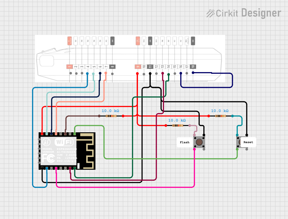


Explore Projects Built with FlipperDevBoard
Common Applications and Use Cases
- Rapid prototyping of electronic circuits
- Testing and debugging embedded systems
- IoT device development
- Educational projects and learning platforms
- Integration with microcontrollers like Arduino, Raspberry Pi, and others
Technical Specifications
The FlipperDevBoard is equipped with a range of features to support diverse project requirements. Below are the key technical details:
General Specifications
| Parameter | Value |
|---|---|
| Manufacturer | Flipper |
| Part ID | ProtoBoard |
| Operating Voltage | 3.3V / 5V |
| Maximum Current | 1A |
| Dimensions | 80mm x 60mm |
| Connectivity Options | GPIO, I2C, SPI, UART, USB |
| Mounting Options | Breadboard-compatible, Screw holes |
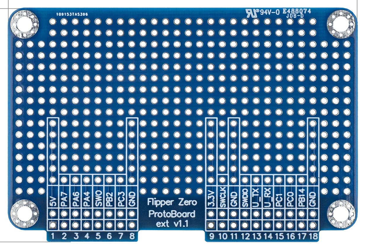
Pin Configuration and Descriptions
The FlipperDevBoard features a standard pinout for easy integration with other components. Below is the pin configuration:
| Pin Number | Pin Name | Description |
|---|---|---|
| 1 | VCC | Power supply input (3.3V or 5V) |
| 2 | GND | Ground |
| 3 | GPIO1 | General-purpose input/output pin 1 |
| 4 | GPIO2 | General-purpose input/output pin 2 |
| 5 | SDA | I2C Data Line |
| 6 | SCL | I2C Clock Line |
| 7 | MOSI | SPI Master Out Slave In |
| 8 | MISO | SPI Master In Slave Out |
| 9 | SCK | SPI Clock |
| 10 | TX | UART Transmit |
| 11 | RX | UART Receive |
| 12 | USB_D+ | USB Data Positive |
| 13 | USB_D- | USB Data Negative |
Usage Instructions
The FlipperDevBoard is designed for ease of use in a variety of electronic projects. Follow the steps below to get started:
How to Use the Component in a Circuit
- Powering the Board: Connect the VCC pin to a 3.3V or 5V power source and the GND pin to ground.
- Connecting Peripherals: Use the GPIO, I2C, SPI, or UART pins to interface with sensors, actuators, or other devices.
- Programming: The board can be programmed using a microcontroller or a development platform like Arduino or Raspberry Pi.
- USB Connectivity: Use the USB_D+ and USB_D- pins for USB communication if required.
Important Considerations and Best Practices
- Ensure the power supply voltage matches the board's operating voltage (3.3V or 5V).
- Avoid exceeding the maximum current rating of 1A to prevent damage.
- Use pull-up resistors for I2C lines (SDA and SCL) if not already integrated into your circuit.
- For SPI communication, ensure proper configuration of the master and slave devices.
- When using UART, match the baud rate of the connected devices.
Example: Connecting to an Arduino UNO
Below is an example of how to use the FlipperDevBoard with an Arduino UNO to read data from an I2C sensor:
#include <Wire.h> // Include the Wire library for I2C communication

#define SENSOR_ADDRESS 0x40 // Replace with your sensor's I2C address

void setup() {
  Wire.begin(); // Initialize I2C communication
  Serial.begin(9600); // Start serial communication for debugging
  Serial.println("FlipperDevBoard I2C Example");
}

void loop() {
  Wire.beginTransmission(SENSOR_ADDRESS); // Start communication with the sensor
  Wire.write(0x00); // Send a command to the sensor (e.g., read data register)
  Wire.endTransmission();

  Wire.requestFrom(SENSOR_ADDRESS, 2); // Request 2 bytes of data from the sensor
  if (Wire.available() == 2) {
    int data = Wire.read() << 8 | Wire.read(); // Combine the two bytes into a single value
    Serial.print("Sensor Data: ");
    Serial.println(data); // Print the sensor data to the serial monitor
  }

  delay(1000); // Wait for 1 second before the next reading
}
Troubleshooting and FAQs
Common Issues Users Might Face
Board Not Powering On:
- Ensure the VCC and GND pins are properly connected.
- Verify that the power supply voltage is within the specified range (3.3V or 5V).
Communication Failure (I2C, SPI, UART):
- Check the wiring and ensure the correct pins are connected.
- Verify the communication protocol settings (e.g., baud rate for UART, clock speed for SPI).
Overheating:
- Ensure the current draw does not exceed 1A.
- Check for short circuits in the connected components.
USB Not Recognized:
- Verify the USB connections (USB_D+ and USB_D-).
- Ensure the correct drivers are installed on your computer.
Solutions and Tips for Troubleshooting
- Use a multimeter to check for proper voltage levels at the VCC and GND pins.
- Test the board with a simple circuit (e.g., an LED and resistor) to confirm basic functionality.
- Double-check the pinout and connections against the documentation.
- If using I2C, scan for connected devices using an I2C scanner sketch to confirm the sensor's address.
By following this documentation, users can effectively utilize the FlipperDevBoard for a wide range of electronic projects.