How to Use 5V 4 Channels Relay Module: Examples, Pinouts, and Specs
Introduction
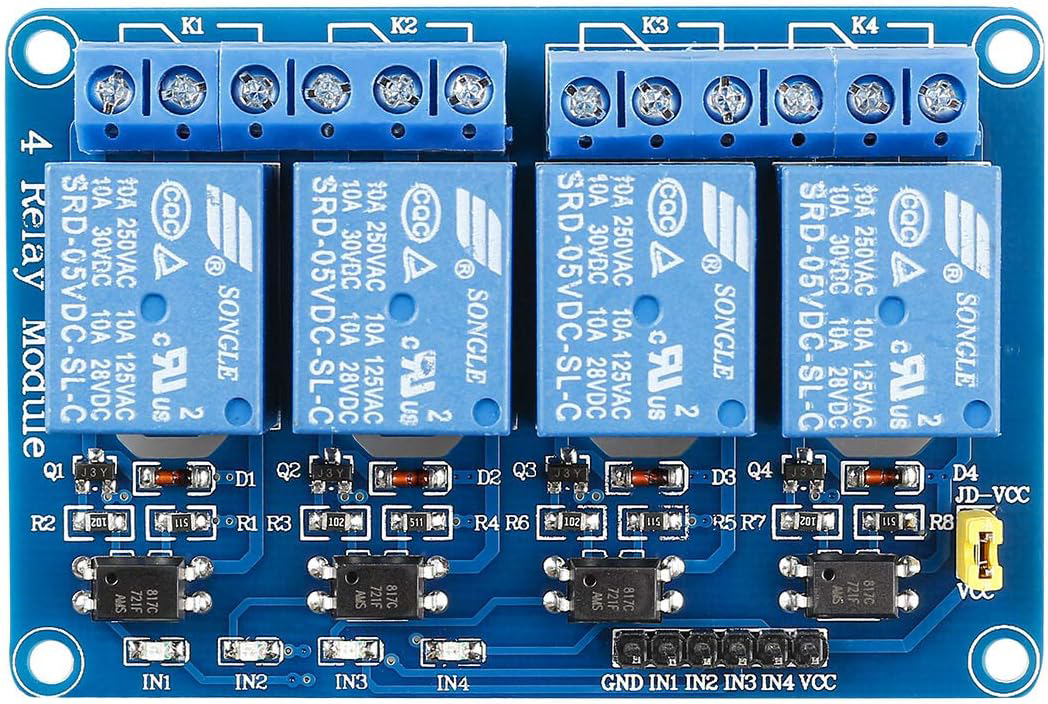
The 5V 4 Channels Relay Module (Manufacturer: SunFounder, Part ID: 520141421286) is an electronic component designed to control high-voltage devices using low-voltage signals. It features four independent relays, each capable of switching AC or DC loads. This module is widely used in home automation, industrial control systems, and DIY projects where electrical isolation and high-power switching are required.
Explore Projects Built with 5V 4 Channels Relay Module


Explore Projects Built with 5V 4 Channels Relay Module
Common Applications
- Home automation (e.g., controlling lights, fans, or appliances)
- Industrial equipment control
- Robotics and IoT projects
- Smart home systems
- Motor and pump control
Technical Specifications
The following table outlines the key technical details of the 5V 4 Channels Relay Module:
| Parameter | Specification |
|---|---|
| Operating Voltage | 5V DC |
| Trigger Voltage | 5V DC (Low-level trigger) |
| Relay Channels | 4 |
| Maximum Load (AC) | 250V AC @ 10A |
| Maximum Load (DC) | 30V DC @ 10A |
| Isolation | Optocoupler isolation |
| Dimensions | 75mm x 55mm x 19mm |
| Weight | ~60g |
Pin Configuration and Descriptions
The module has two sets of pins: Input Pins for control signals and Output Terminals for connecting the load. Below is the pin configuration:
Input Pins
| Pin | Label | Description |
|---|---|---|
| 1 | VCC | 5V DC power supply for the module |
| 2 | GND | Ground connection |
| 3 | IN1 | Control signal for Relay 1 (Active Low) |
| 4 | IN2 | Control signal for Relay 2 (Active Low) |
| 5 | IN3 | Control signal for Relay 3 (Active Low) |
| 6 | IN4 | Control signal for Relay 4 (Active Low) |
Output Terminals (for each relay)
| Terminal | Label | Description |
|---|---|---|
| 1 | COM | Common terminal |
| 2 | NO | Normally Open terminal |
| 3 | NC | Normally Closed terminal |
- COM: Connects to the common point of the relay.
- NO: Normally open; connects to COM when the relay is activated.
- NC: Normally closed; connects to COM when the relay is deactivated.
Usage Instructions
How to Use the Module in a Circuit
- Power the Module: Connect the VCC pin to a 5V DC power source and the GND pin to ground.
- Connect Control Signals: Use a microcontroller (e.g., Arduino UNO) to send control signals to the IN1–IN4 pins. A LOW signal activates the corresponding relay.
- Connect the Load:
- For each relay, connect the load to the COM and NO terminals if you want the load to be off by default and turn on when the relay is activated.
- Use the COM and NC terminals if you want the load to be on by default and turn off when the relay is activated.
- Ensure Electrical Isolation: The module uses optocouplers for isolation, but ensure proper grounding and separation between the low-voltage and high-voltage sides.
Example: Connecting to an Arduino UNO
Below is an example of how to control the 5V 4 Channels Relay Module using an Arduino UNO:
Circuit Connections
- Connect the module's VCC to the Arduino's 5V pin.
- Connect the module's GND to the Arduino's GND pin.
- Connect the module's IN1, IN2, IN3, and IN4 to Arduino digital pins (e.g., D2, D3, D4, D5).
Arduino Code
// Define relay control pins
#define RELAY1 2  // Pin connected to IN1
#define RELAY2 3  // Pin connected to IN2
#define RELAY3 4  // Pin connected to IN3
#define RELAY4 5  // Pin connected to IN4

void setup() {
  // Set relay pins as outputs
  pinMode(RELAY1, OUTPUT);
  pinMode(RELAY2, OUTPUT);
  pinMode(RELAY3, OUTPUT);
  pinMode(RELAY4, OUTPUT);

  // Initialize all relays to OFF state
  digitalWrite(RELAY1, HIGH); // HIGH = Relay OFF (Active Low)
  digitalWrite(RELAY2, HIGH);
  digitalWrite(RELAY3, HIGH);
  digitalWrite(RELAY4, HIGH);
}

void loop() {
  // Example: Turn relays ON and OFF with a delay
  digitalWrite(RELAY1, LOW);  // Turn Relay 1 ON
  delay(1000);                // Wait 1 second
  digitalWrite(RELAY1, HIGH); // Turn Relay 1 OFF
  delay(1000);                // Wait 1 second

  digitalWrite(RELAY2, LOW);  // Turn Relay 2 ON
  delay(1000);
  digitalWrite(RELAY2, HIGH); // Turn Relay 2 OFF
  delay(1000);

  digitalWrite(RELAY3, LOW);  // Turn Relay 3 ON
  delay(1000);
  digitalWrite(RELAY3, HIGH); // Turn Relay 3 OFF
  delay(1000);

  digitalWrite(RELAY4, LOW);  // Turn Relay 4 ON
  delay(1000);
  digitalWrite(RELAY4, HIGH); // Turn Relay 4 OFF
  delay(1000);
}
Important Considerations and Best Practices
- Power Supply: Ensure the module is powered with a stable 5V DC supply.
- Load Ratings: Do not exceed the maximum load ratings (250V AC @ 10A or 30V DC @ 10A).
- Isolation: Maintain proper isolation between the low-voltage control side and the high-voltage load side to prevent damage or hazards.
- Active Low Trigger: Remember that the relays are activated by a LOW signal.
Troubleshooting and FAQs
Common Issues and Solutions
Relays Not Activating:
- Ensure the module is powered with 5V DC.
- Verify that the control signals (IN1–IN4) are correctly connected and set to LOW to activate the relays.
- Check for loose or incorrect wiring.
Load Not Switching:
- Confirm that the load is properly connected to the COM and NO/NC terminals.
- Verify that the load does not exceed the relay's maximum ratings.
Module Overheating:
- Ensure the load current does not exceed 10A.
- Use proper heat dissipation methods if the module is used for extended periods.
Interference with Microcontroller:
- Use separate power supplies for the relay module and the microcontroller if interference occurs.
- Add decoupling capacitors to stabilize the power supply.
FAQs
Q1: Can I use this module with a 3.3V microcontroller?
A1: No, the module requires a 5V control signal. Use a level shifter or transistor circuit to interface with 3.3V microcontrollers.
Q2: Can I control all four relays simultaneously?
A2: Yes, you can activate all four relays at the same time, provided the power supply can handle the current draw.
Q3: Is the module safe for high-voltage applications?
A3: Yes, the module is designed for high-voltage applications, but proper precautions must be taken to ensure safety and compliance with local regulations.
Q4: What is the purpose of the optocouplers?
A4: The optocouplers provide electrical isolation between the control side (low voltage) and the load side (high voltage), enhancing safety and preventing damage to the microcontroller.