Cirkit Designer Logo
Cirkit Designer
Your all-in-one circuit design IDE
Home / 
Component Documentation

How to Use SMPS_9V_UP15S09: Examples, Pinouts, and Specs

Image of SMPS_9V_UP15S09
Cirkit Designer LogoDesign with SMPS_9V_UP15S09 in Cirkit Designer

Introduction

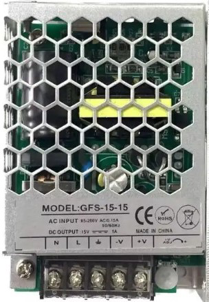
The SMPS_9V_UP15S09 is a Switching Mode Power Supply (SMPS) component that provides a stable and regulated 9V output voltage. This component utilizes the UP15S09 module, which is known for its efficiency and reliability in converting a wider input voltage range to a steady output voltage. Common applications for this SMPS include powering electronic circuits, microcontrollers like Arduino UNO, and other devices that require a 9V power source.

Explore Projects Built with SMPS_9V_UP15S09

Use Cirkit Designer to design, explore, and prototype these projects online. Some projects support real-time simulation. Click "Open Project" to start designing instantly!
Battery-Powered UPS with Step-Down Buck Converter and BMS
Image of Mini ups: A project utilizing SMPS_9V_UP15S09 in a practical application
This circuit is a power management system that steps down a 240V AC input to a lower DC voltage using a buck converter, which then powers a 40W UPS. The UPS is controlled by a rocker switch and is backed up by a battery management system (BMS) connected to three 3.7V batteries in series, ensuring continuous power supply.
Cirkit Designer LogoOpen Project in Cirkit Designer
12V UPS System with Dual 18650 Li-ion Battery Backup and Voltage Regulation
Image of Power supply: A project utilizing SMPS_9V_UP15S09 in a practical application
This circuit is designed to provide an uninterruptible power supply (UPS) system with a 12V DC output. It includes a 12V 5A power supply connected to an AC source through a toggle switch, which charges a pair of 18650 Li-ion batteries via a voltage regulator (XL4016). The UPS module ensures a continuous power supply to the load by switching between the power supply and the battery bank.
Cirkit Designer LogoOpen Project in Cirkit Designer
Modular Power Distribution System with Multiple SMPS Units and 120V Outlet
Image of Cellion-Tesla: A project utilizing SMPS_9V_UP15S09 in a practical application
This circuit is designed to convert 240V AC power to both 12V and 24V DC outputs using multiple SMPS units. Terminal blocks are used to organize and distribute the power, while a 120V outlet provides additional AC power access. The circuit is likely used for powering various electronic devices that require different voltage levels.
Cirkit Designer LogoOpen Project in Cirkit Designer
Battery-Powered Adjustable Voltage Regulator with Li-ion 18650 Batteries and BMS
Image of mini ups: A project utilizing SMPS_9V_UP15S09 in a practical application
This circuit is a power management system that uses four Li-ion 18650 batteries connected to a 2S 30A BMS for battery management and protection. The system includes step-up and step-down voltage regulators to provide adjustable output voltages, controlled by a rocker switch, and multiple DC jacks for power input and output.
Cirkit Designer LogoOpen Project in Cirkit Designer

Explore Projects Built with SMPS_9V_UP15S09

Use Cirkit Designer to design, explore, and prototype these projects online. Some projects support real-time simulation. Click "Open Project" to start designing instantly!
Image of Mini ups: A project utilizing SMPS_9V_UP15S09 in a practical application
Battery-Powered UPS with Step-Down Buck Converter and BMS
This circuit is a power management system that steps down a 240V AC input to a lower DC voltage using a buck converter, which then powers a 40W UPS. The UPS is controlled by a rocker switch and is backed up by a battery management system (BMS) connected to three 3.7V batteries in series, ensuring continuous power supply.
Cirkit Designer LogoOpen Project in Cirkit Designer
Image of Power supply: A project utilizing SMPS_9V_UP15S09 in a practical application
12V UPS System with Dual 18650 Li-ion Battery Backup and Voltage Regulation
This circuit is designed to provide an uninterruptible power supply (UPS) system with a 12V DC output. It includes a 12V 5A power supply connected to an AC source through a toggle switch, which charges a pair of 18650 Li-ion batteries via a voltage regulator (XL4016). The UPS module ensures a continuous power supply to the load by switching between the power supply and the battery bank.
Cirkit Designer LogoOpen Project in Cirkit Designer
Image of Cellion-Tesla: A project utilizing SMPS_9V_UP15S09 in a practical application
Modular Power Distribution System with Multiple SMPS Units and 120V Outlet
This circuit is designed to convert 240V AC power to both 12V and 24V DC outputs using multiple SMPS units. Terminal blocks are used to organize and distribute the power, while a 120V outlet provides additional AC power access. The circuit is likely used for powering various electronic devices that require different voltage levels.
Cirkit Designer LogoOpen Project in Cirkit Designer
Image of mini ups: A project utilizing SMPS_9V_UP15S09 in a practical application
Battery-Powered Adjustable Voltage Regulator with Li-ion 18650 Batteries and BMS
This circuit is a power management system that uses four Li-ion 18650 batteries connected to a 2S 30A BMS for battery management and protection. The system includes step-up and step-down voltage regulators to provide adjustable output voltages, controlled by a rocker switch, and multiple DC jacks for power input and output.
Cirkit Designer LogoOpen Project in Cirkit Designer

Technical Specifications

General Features

  • Output Voltage: 9V DC
  • Input Voltage Range: 100V AC to 240V AC, 50/60Hz
  • Output Current: Up to 1.5A
  • Efficiency: >80% at full load
  • Protection: Overcurrent, Overvoltage, Short Circuit, Thermal
  • Operating Temperature: -10°C to +60°C
  • Safety Standards: Compliant with relevant international standards

Pin Configuration and Descriptions

Pin Number Description Notes
1 AC Input Live (L) Connect to live wire of AC mains
2 AC Input Neutral (N) Connect to neutral wire of AC mains
3 Ground (⏚) Connect to earth ground if available
4 DC Output (+9V) Positive output terminal
5 DC Output (GND) Ground reference for output

Usage Instructions

Connecting to a Circuit

  1. AC Input Connection:

    • Ensure the power source matches the input specifications of the SMPS.
    • Connect the live and neutral wires to pins 1 and 2, respectively.
    • If available, connect the ground wire to pin 3 for safety.
  2. DC Output Connection:

    • Connect the positive output (pin 4) to the positive rail of your circuit.
    • Connect the ground output (pin 5) to the ground rail of your circuit.

Best Practices

  • Always disconnect the power before making any connections to avoid electric shock.
  • Use a fuse on the AC input for additional safety.
  • Ensure proper ventilation around the SMPS to prevent overheating.
  • Do not exceed the rated output current to avoid damage to the SMPS.

Troubleshooting and FAQs

Q: What should I do if the SMPS is not powering on? A: Check the AC mains connection for proper voltage and ensure the fuse is not blown.

Q: The output voltage is fluctuating, what could be the cause? A: Ensure that the load does not exceed the rated current and that there are no short circuits in your application.

Q: Can I use this SMPS with an Arduino UNO? A: Yes, the SMPS can be used to power an Arduino UNO, which typically operates at 7-12V.

Q: How can I reduce electromagnetic interference (EMI) from the SMPS? A: Use proper shielding and grounding techniques, and keep the SMPS away from sensitive components.

Q: The SMPS is overheating, what should I do? A: Ensure adequate ventilation and check if the load is within the specified limits.

Example Arduino UNO Connection

// No specific code is required for powering the Arduino UNO with the SMPS.
// However, ensure that the 9V output from the SMPS is connected to the
// VIN pin on the Arduino and the ground is connected to one of the GND pins.

void setup() {
  // Initialize digital pin LED_BUILTIN as an output.
  pinMode(LED_BUILTIN, OUTPUT);
}

void loop() {
  // Turn the LED on (HIGH is the voltage level)
  digitalWrite(LED_BUILTIN, HIGH);
  // Wait for a second
  delay(1000);
  // Turn the LED off by making the voltage LOW
  digitalWrite(LED_BUILTIN, LOW);
   // Wait for a second
  delay(1000);
}

Note: The above code is a simple blink program to test the power supply functionality with an Arduino UNO. The SMPS_9V_UP15S09 should be connected to the VIN and GND pins on the Arduino for power.

For further assistance or technical support, please contact the manufacturer, GPS, with the part ID: GPS.