Cirkit Designer Logo
Cirkit Designer
Your all-in-one circuit design IDE
Home / 
Component Documentation

How to Use FS-CT6B Receiver: Examples, Pinouts, and Specs

Image of FS-CT6B Receiver
Cirkit Designer LogoDesign with FS-CT6B Receiver in Cirkit Designer

Introduction

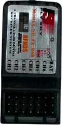
The FS-CT6B Receiver is a 6-channel 2.4GHz radio receiver designed by Fly Sky, primarily used in remote control (RC) systems for hobbyist and enthusiast applications. It is capable of receiving signals from a compatible Fly Sky transmitter, which it then translates into control commands for various output devices such as servos, electronic speed controllers (ESCs), and lights in RC vehicles, aircraft, boats, and other models.

Explore Projects Built with FS-CT6B Receiver

Use Cirkit Designer to design, explore, and prototype these projects online. Some projects support real-time simulation. Click "Open Project" to start designing instantly!
Satellite-Based Timing and Navigation System with SDR and Atomic Clock Synchronization
Image of GPS 시스템 측정 구성도_Confirm: A project utilizing FS-CT6B Receiver in a practical application
This circuit appears to be a complex system involving power supply management, GPS and timing synchronization, and data communication. It includes a SI-TEX G1 Satellite Compass for GPS data, an XHTF1021 Atomic Rubidium Clock for precise timing, and Ettus USRP B200 units for software-defined radio communication. Power is supplied through various SMPS units and distributed via terminal blocks and DC jacks. Data communication is facilitated by Beelink MINI S12 N95 computers, RS232 splitters, and a 1000BASE-T Media Converter for network connectivity. RF Directional Couplers are used to interface antennas with the USRP units, and the entire system is likely contained within cases for protection and organization.
Cirkit Designer LogoOpen Project in Cirkit Designer
FTDI to UART Adapter with J26 Connector
Image of J26 CLOSEUP: A project utilizing FS-CT6B Receiver in a practical application
This circuit connects an FTDI USB-to-serial converter to a standard serial interface via a J26 connector. It facilitates serial communication by linking the ground, transmit, receive, data terminal ready, and request to send signals between the FTDI chip and the J26 connector.
Cirkit Designer LogoOpen Project in Cirkit Designer
Arduino Mega 2560 Controlled Multi-Motor Drive System
Image of ISRO rover : A project utilizing FS-CT6B Receiver in a practical application
This circuit appears to be a multi-channel motor control system using an Arduino Mega 2560 as the central processing unit. The Arduino interfaces with a radio receiver (FS-CT6B) to receive control signals and drives multiple motors through individual motor driver modules. A step-down buck converter is used to regulate the voltage from a 12V battery to power the system, and the Arduino's TX/RX pins are used to communicate with the motor drivers for speed and direction control.
Cirkit Designer LogoOpen Project in Cirkit Designer
Battery-Powered Motor Control System with FlySky Receiver and Cytron Motor Driver
Image of Fighter: A project utilizing FS-CT6B Receiver in a practical application
The circuit is a motor control system that uses a FlySky FS-IA6 receiver to control four motors via a Cytron MDDS30 motor driver. The system is powered by a LiPo battery, and the receiver sends control signals to the motor driver, which then drives the motors accordingly.
Cirkit Designer LogoOpen Project in Cirkit Designer

Explore Projects Built with FS-CT6B Receiver

Use Cirkit Designer to design, explore, and prototype these projects online. Some projects support real-time simulation. Click "Open Project" to start designing instantly!
Image of GPS 시스템 측정 구성도_Confirm: A project utilizing FS-CT6B Receiver in a practical application
Satellite-Based Timing and Navigation System with SDR and Atomic Clock Synchronization
This circuit appears to be a complex system involving power supply management, GPS and timing synchronization, and data communication. It includes a SI-TEX G1 Satellite Compass for GPS data, an XHTF1021 Atomic Rubidium Clock for precise timing, and Ettus USRP B200 units for software-defined radio communication. Power is supplied through various SMPS units and distributed via terminal blocks and DC jacks. Data communication is facilitated by Beelink MINI S12 N95 computers, RS232 splitters, and a 1000BASE-T Media Converter for network connectivity. RF Directional Couplers are used to interface antennas with the USRP units, and the entire system is likely contained within cases for protection and organization.
Cirkit Designer LogoOpen Project in Cirkit Designer
Image of J26 CLOSEUP: A project utilizing FS-CT6B Receiver in a practical application
FTDI to UART Adapter with J26 Connector
This circuit connects an FTDI USB-to-serial converter to a standard serial interface via a J26 connector. It facilitates serial communication by linking the ground, transmit, receive, data terminal ready, and request to send signals between the FTDI chip and the J26 connector.
Cirkit Designer LogoOpen Project in Cirkit Designer
Image of ISRO rover : A project utilizing FS-CT6B Receiver in a practical application
Arduino Mega 2560 Controlled Multi-Motor Drive System
This circuit appears to be a multi-channel motor control system using an Arduino Mega 2560 as the central processing unit. The Arduino interfaces with a radio receiver (FS-CT6B) to receive control signals and drives multiple motors through individual motor driver modules. A step-down buck converter is used to regulate the voltage from a 12V battery to power the system, and the Arduino's TX/RX pins are used to communicate with the motor drivers for speed and direction control.
Cirkit Designer LogoOpen Project in Cirkit Designer
Image of Fighter: A project utilizing FS-CT6B Receiver in a practical application
Battery-Powered Motor Control System with FlySky Receiver and Cytron Motor Driver
The circuit is a motor control system that uses a FlySky FS-IA6 receiver to control four motors via a Cytron MDDS30 motor driver. The system is powered by a LiPo battery, and the receiver sends control signals to the motor driver, which then drives the motors accordingly.
Cirkit Designer LogoOpen Project in Cirkit Designer

Common Applications and Use Cases

  • Radio Controlled (RC) Aircraft
  • RC Cars and Trucks
  • RC Boats
  • Robotics and DIY Projects
  • Educational Purposes

Technical Specifications

Key Technical Details

  • Channels: 6
  • Frequency Range: 2.4GHz ISM Frequency Range
  • Modulation Type: GFSK
  • Sensitivity: 1024
  • RF Receiver Sensitivity: -105dBm
  • Power: 4.5 - 6V DC
  • Size: 52mm x 35mm x 15mm
  • Weight: 18g

Pin Configuration and Descriptions

Pin Number Function Description
1 Channel 1 Typically used for throttle control
2 Channel 2 Typically used for aileron control
3 Channel 3 Typically used for elevator control
4 Channel 4 Typically used for rudder control
5 Channel 5 Auxiliary channel, often used for gear or lights
6 Channel 6 Auxiliary channel, often used for flaps
BAT Power Supply Connect to 4.5 - 6V power source

Usage Instructions

How to Use the Component in a Circuit

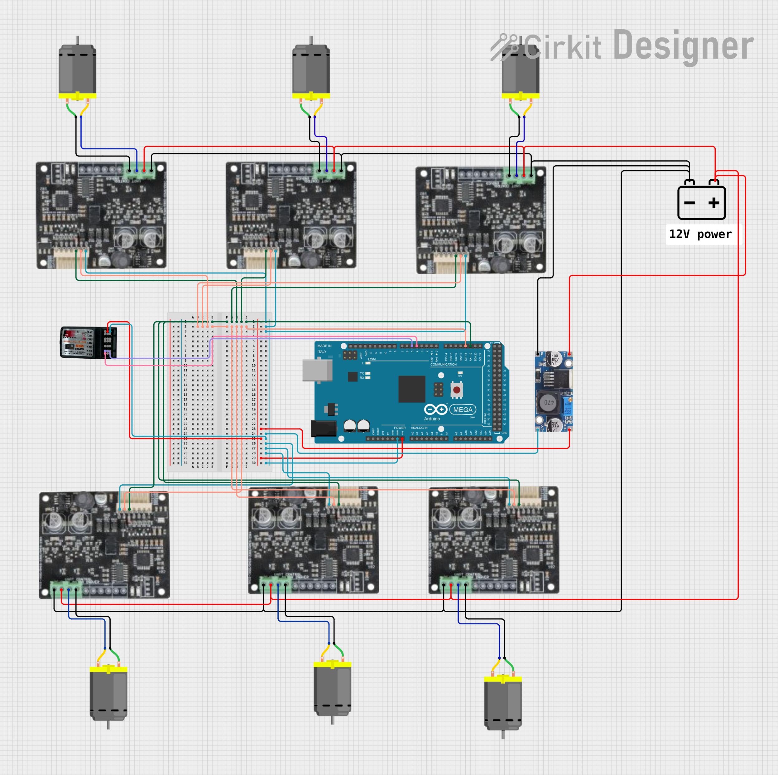
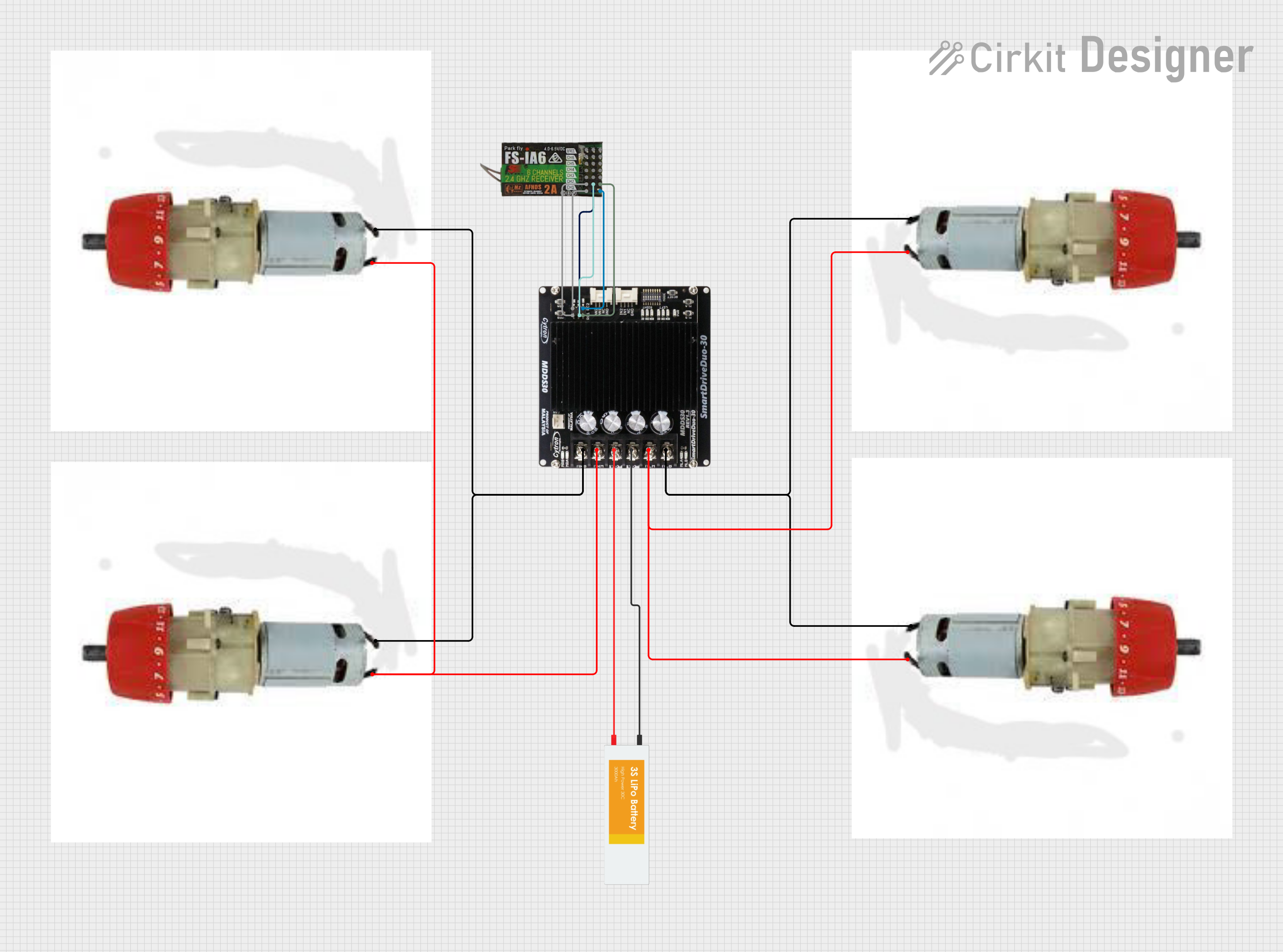
  1. Power Connection: Connect a 4.5 - 6V power source to the BAT pin of the FS-CT6B Receiver.
  2. Servo Connections: Connect servos or ESCs to the appropriate channel pins. Ensure that the signal wire (usually white or orange) aligns with the signal pin on the receiver.
  3. Binding: Before use, the receiver must be bound to a compatible Fly Sky transmitter. Follow the binding instructions provided by the manufacturer.
  4. Testing: Test each channel by operating the corresponding control on the transmitter to ensure proper response from the connected servos or ESCs.

Important Considerations and Best Practices

  • Antenna Placement: Ensure the receiver's antenna is placed away from metal components and wires to avoid signal interference.
  • Voltage Regulation: If using a power source greater than 6V, a voltage regulator must be used to avoid damaging the receiver.
  • Binding: The receiver must be bound to the transmitter before it will operate. This process is unique to the transmitter model and should be done according to the manufacturer's instructions.
  • Range Testing: Perform a range test to ensure the receiver maintains a strong signal with the transmitter at the intended operating distance.

Troubleshooting and FAQs

Common Issues

  • No Response from Servos/ESCs: Ensure the receiver is properly bound to the transmitter and that the power source is within the specified voltage range.
  • Intermittent Signal: Check for obstructions or potential sources of interference. Ensure the antenna is properly positioned.
  • Short Range: Perform a range test and check the antenna for damage or poor placement.

Solutions and Tips for Troubleshooting

  • Rebinding: If the receiver is not responding, try rebinding it to the transmitter.
  • Power Check: Verify that the power source is connected correctly and supplying the correct voltage.
  • Antenna Inspection: Inspect the antenna for damage and ensure it is not obstructed or coiled.

FAQs

Q: Can I use the FS-CT6B Receiver with any transmitter? A: No, the receiver must be used with a compatible Fly Sky transmitter that operates on the 2.4GHz frequency.

Q: How do I know if the receiver is bound to the transmitter? A: A solid LED light on the receiver typically indicates a successful bind. Refer to the manufacturer's instructions for specific details.

Q: What should I do if I experience interference or signal loss? A: Check for sources of interference, ensure the antenna is properly placed, and consider performing a range test to identify the issue.

Q: Can I use rechargeable batteries to power the receiver? A: Yes, as long as the voltage is within the specified range of 4.5 - 6V.

Example Code for Arduino UNO Connection

// This example assumes you have a servo connected to channel 1 of the FS-CT6B Receiver.
#include <Servo.h>

Servo myservo;  // create servo object to control a servo

void setup() {
  myservo.attach(9);  // attaches the servo on pin 9 to the servo object
}

void loop() {
  int val = pulseIn(2, HIGH);  // reads the pulse width on pin 2 (connected to channel 1 of the receiver)
  val = map(val, 1000, 2000, 0, 180);  // scale it to use with the servo (value between 0 and 180)
  myservo.write(val);  // sets the servo position according to the scaled value
  delay(15);  // waits for the servo to get there
}

Note: The pulseIn function reads the duration of a pulse on a pin. The map function then scales the input from the receiver (which is typically between 1000 and 2000 microseconds for RC receivers) to a range suitable for servo control (0 to 180 degrees).

Remember: Always ensure that the Arduino and the FS-CT6B Receiver are powered appropriately and that the ground of the receiver is connected to the ground of the Arduino.