How to Use RTD2660H : Examples, Pinouts, and Specs
Introduction
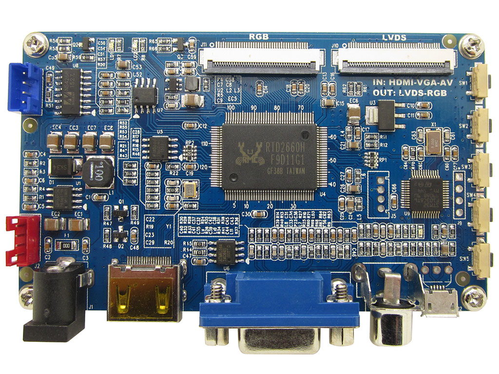
The RTD2660H is a high-performance display driver IC designed for driving LCD panels. It supports a wide range of display resolutions, making it versatile for various applications. With integrated power management and advanced features, the RTD2660H is commonly used in consumer electronics such as smartphones, tablets, portable monitors, and other display-based devices.
Explore Projects Built with RTD2660H


Explore Projects Built with RTD2660H
Common Applications and Use Cases
- Smartphones and tablets
- Portable LCD monitors
- Digital photo frames
- Embedded systems with display requirements
- Industrial control panels
Technical Specifications
Key Technical Details
- Core Voltage: 3.3V
- Input Voltage Range: 3.0V to 3.6V
- Supported Resolutions: Up to 1920x1080 (Full HD)
- Integrated Power Management: Yes
- Interface Support: LVDS, TTL, and HDMI
- Operating Temperature Range: -20°C to 70°C
- Package Type: LQFP-128 (Low-Profile Quad Flat Package)
Pin Configuration and Descriptions
The RTD2660H comes in an LQFP-128 package with the following key pin assignments:
| Pin Number | Pin Name | Description |
|---|---|---|
| 1-8 | LVDS_TX[0:7] | LVDS data output channels for driving LCD panels. |
| 9-16 | LVDS_CLK | LVDS clock output for synchronization. |
| 17-24 | HDMI_RX[0:7] | HDMI input data channels for receiving video signals. |
| 25-32 | HDMI_CLK | HDMI clock input for synchronization. |
| 33-40 | TTL_DATA[0:7] | TTL data output channels for LCD panels. |
| 41-48 | TTL_CLK | TTL clock output for synchronization. |
| 49-56 | VDD | Power supply pins (3.3V). |
| 57-64 | GND | Ground pins. |
| 65-72 | I2C_SCL, I2C_SDA | I2C interface for communication and configuration. |
| 73-80 | RESET | Reset pin to initialize the IC. Active low. |
| 81-88 | PWM_OUT | Pulse-width modulation output for backlight control. |
| 89-96 | GPIO[0:7] | General-purpose input/output pins for custom functionality. |
| 97-104 | TEST | Test pins for factory use. Leave unconnected in normal operation. |
| 105-112 | OSC_IN, OSC_OUT | Oscillator input and output for clock generation. |
| 113-120 | VCORE | Core voltage supply pins (1.2V). |
| 121-128 | NC | No-connect pins. Leave unconnected. |
Usage Instructions
How to Use the RTD2660H in a Circuit
- Power Supply: Connect the VDD pins to a stable 3.3V power source and the VCORE pins to a 1.2V supply. Ensure proper decoupling capacitors are placed near the power pins to reduce noise.
- Reset: Use the RESET pin to initialize the IC. Pull the pin low for at least 10ms during power-up, then release it to start normal operation.
- Interface Selection: Configure the input interface (HDMI, LVDS, or TTL) based on your application. Use the I2C interface to set the desired mode and resolution.
- Backlight Control: Connect the PWM_OUT pin to the backlight driver circuit to control the brightness of the LCD panel.
- Clock Source: Provide an external clock signal to the OSC_IN pin or use the internal oscillator for clock generation.
- I2C Communication: Use the I2C_SCL and I2C_SDA pins to communicate with the RTD2660H for configuration and control. The default I2C address is typically 0x50.
Important Considerations and Best Practices
- Decoupling Capacitors: Place decoupling capacitors (e.g., 0.1µF) close to the power pins to minimize noise and ensure stable operation.
- Signal Integrity: Use proper PCB layout techniques to maintain signal integrity, especially for high-speed interfaces like HDMI and LVDS.
- Thermal Management: Ensure adequate heat dissipation by using a proper heatsink or thermal pad if the IC operates in high-temperature environments.
- Unused Pins: Leave unused pins (e.g., NC and TEST) unconnected to avoid interference.
Example: Connecting RTD2660H to an Arduino UNO
While the RTD2660H is not directly compatible with Arduino UNO due to its complexity, the I2C interface can be used for basic communication. Below is an example Arduino sketch to configure the RTD2660H via I2C:
#include <Wire.h> // Include the Wire library for I2C communication

#define RTD2660H_I2C_ADDRESS 0x50 // Default I2C address of RTD2660H

void setup() {
  Wire.begin(); // Initialize I2C communication
  Serial.begin(9600); // Initialize serial communication for debugging

  // Send a configuration command to RTD2660H
  Wire.beginTransmission(RTD2660H_I2C_ADDRESS);
  Wire.write(0x01); // Example register address
  Wire.write(0x80); // Example data to configure the IC
  Wire.endTransmission();

  Serial.println("RTD2660H configured successfully.");
}

void loop() {
  // Add code here to read or write additional data if needed
}
Troubleshooting and FAQs
Common Issues and Solutions
No Display Output
- Cause: Incorrect power supply or missing connections.
- Solution: Verify that the VDD and VCORE pins are connected to the correct voltage levels. Check all signal connections.
Flickering or Distorted Display
- Cause: Poor signal integrity or incorrect configuration.
- Solution: Ensure proper PCB layout and shielding for high-speed signals. Use the I2C interface to verify and adjust the configuration.
Backlight Not Working
- Cause: PWM_OUT pin not connected or misconfigured.
- Solution: Check the backlight driver circuit and ensure the PWM_OUT pin is generating the correct signal.
I2C Communication Fails
- Cause: Incorrect I2C address or wiring.
- Solution: Verify the I2C address and ensure proper pull-up resistors are used on the I2C lines.
FAQs
Q1: Can the RTD2660H drive 4K displays?
A1: No, the RTD2660H supports resolutions up to 1920x1080 (Full HD).
Q2: Is an external oscillator required?
A2: No, the RTD2660H has an internal oscillator, but an external clock can be used for higher precision.
Q3: Can I use the RTD2660H with a Raspberry Pi?
A3: Yes, the RTD2660H can interface with a Raspberry Pi via HDMI or I2C for configuration.
Q4: What is the typical power consumption of the RTD2660H?
A4: The power consumption depends on the application, but it typically ranges from 1W to 2W under normal operation.
Q5: How do I update the firmware of the RTD2660H?
A5: Firmware updates are typically performed via the I2C interface or a dedicated programming tool provided by the manufacturer.