Cirkit Designer Logo
Cirkit Designer
Your all-in-one circuit design IDE
Home / 
Component Documentation

How to Use ESC Basic: Examples, Pinouts, and Specs

Image of ESC Basic
Cirkit Designer LogoDesign with ESC Basic in Cirkit Designer

Introduction

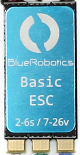
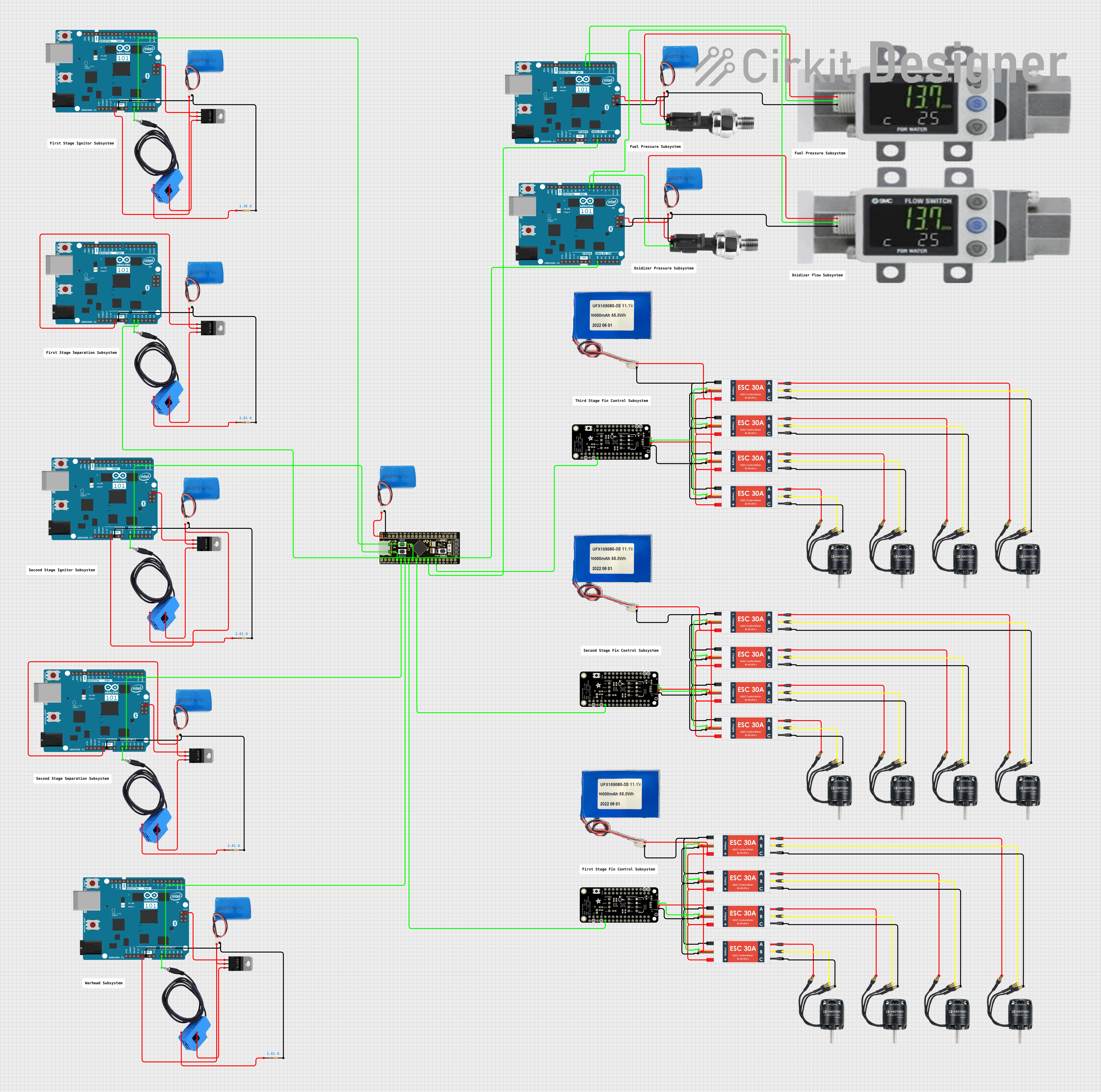
The ESC Basic by Bluerobotics is an Electronic Speed Controller designed to regulate the speed, direction, and braking of brushless DC motors. It is a critical component in electric vehicles, drones, and other motor-driven systems, enabling precise control of motor performance. The ESC Basic interprets input signals from a receiver or microcontroller and adjusts the motor's power output accordingly, ensuring smooth and efficient operation.

Explore Projects Built with ESC Basic

Use Cirkit Designer to design, explore, and prototype these projects online. Some projects support real-time simulation. Click "Open Project" to start designing instantly!
Multi-ESC BLDC Motor Control System with Adafruit 9-DoF Sensor Feedback
Image of MRBM_WiringDiagram: A project utilizing ESC Basic in a practical application
This circuit consists of multiple Electronic Speed Controllers (ESCs) connected to Brushless DC (BLDC) motors and powered by Lithium-ion batteries. The ESCs receive control signals from Adafruit Precision 9-DoF ISM330DHCX + LIS3MDL FeatherWings, which are likely used for motion sensing and control. Additionally, the circuit includes an STM32F4 BlackPill microcontroller, current sensors, MOSFETs, resistors, and other sensors, indicating a complex control system possibly for a drone or a robotic application.
Cirkit Designer LogoOpen Project in Cirkit Designer
Quadcopter BLDC Motor Control System with Radio Receiver
Image of rc car: A project utilizing ESC Basic in a practical application
This circuit is designed to control four Brushless DC (BLDC) motors using corresponding Electronic Speed Controllers (ESCs). Each ESC receives power from a shared LiPo battery and control signals from an FS-CT6B receiver, which likely receives input from a remote transmitter for wireless control. The ESCs regulate the power supplied to the motors based on the received signals, enabling precise speed and direction control of the motors, typically used in applications such as drones or remote-controlled vehicles.
Cirkit Designer LogoOpen Project in Cirkit Designer
ESP32 and ADXL343-Based Battery-Powered Accelerometer with SPI Communication
Image of vibration module: A project utilizing ESC Basic in a practical application
This circuit features an ESP32 microcontroller interfaced with an ADXL343 accelerometer via SPI communication, powered by a 12V battery regulated down to 5V and 8V using 7805 and 7808 voltage regulators. The ESP32 reads accelerometer data and outputs it via serial communication, with additional components including a pushbutton and a rocker switch for user input.
Cirkit Designer LogoOpen Project in Cirkit Designer
ESP32-Based Fingerprint Access Control System with Solenoid Lock and IR Sensor
Image of lalala: A project utilizing ESC Basic in a practical application
This circuit features an ESP32 microcontroller as the central processing unit, interfaced with a variety of components. It controls a 5V relay to actuate a 12V solenoid lock, indicating its use in a security or access control system. The ESP32 also interfaces with an R307 fingerprint sensor for biometric authentication, an IR sensor for proximity detection, a buzzer for audible alerts, a push switch for manual input, and a 16x2 I2C LCD for displaying information.
Cirkit Designer LogoOpen Project in Cirkit Designer

Explore Projects Built with ESC Basic

Use Cirkit Designer to design, explore, and prototype these projects online. Some projects support real-time simulation. Click "Open Project" to start designing instantly!
Image of MRBM_WiringDiagram: A project utilizing ESC Basic in a practical application
Multi-ESC BLDC Motor Control System with Adafruit 9-DoF Sensor Feedback
This circuit consists of multiple Electronic Speed Controllers (ESCs) connected to Brushless DC (BLDC) motors and powered by Lithium-ion batteries. The ESCs receive control signals from Adafruit Precision 9-DoF ISM330DHCX + LIS3MDL FeatherWings, which are likely used for motion sensing and control. Additionally, the circuit includes an STM32F4 BlackPill microcontroller, current sensors, MOSFETs, resistors, and other sensors, indicating a complex control system possibly for a drone or a robotic application.
Cirkit Designer LogoOpen Project in Cirkit Designer
Image of rc car: A project utilizing ESC Basic in a practical application
Quadcopter BLDC Motor Control System with Radio Receiver
This circuit is designed to control four Brushless DC (BLDC) motors using corresponding Electronic Speed Controllers (ESCs). Each ESC receives power from a shared LiPo battery and control signals from an FS-CT6B receiver, which likely receives input from a remote transmitter for wireless control. The ESCs regulate the power supplied to the motors based on the received signals, enabling precise speed and direction control of the motors, typically used in applications such as drones or remote-controlled vehicles.
Cirkit Designer LogoOpen Project in Cirkit Designer
Image of vibration module: A project utilizing ESC Basic in a practical application
ESP32 and ADXL343-Based Battery-Powered Accelerometer with SPI Communication
This circuit features an ESP32 microcontroller interfaced with an ADXL343 accelerometer via SPI communication, powered by a 12V battery regulated down to 5V and 8V using 7805 and 7808 voltage regulators. The ESP32 reads accelerometer data and outputs it via serial communication, with additional components including a pushbutton and a rocker switch for user input.
Cirkit Designer LogoOpen Project in Cirkit Designer
Image of lalala: A project utilizing ESC Basic in a practical application
ESP32-Based Fingerprint Access Control System with Solenoid Lock and IR Sensor
This circuit features an ESP32 microcontroller as the central processing unit, interfaced with a variety of components. It controls a 5V relay to actuate a 12V solenoid lock, indicating its use in a security or access control system. The ESP32 also interfaces with an R307 fingerprint sensor for biometric authentication, an IR sensor for proximity detection, a buzzer for audible alerts, a push switch for manual input, and a 16x2 I2C LCD for displaying information.
Cirkit Designer LogoOpen Project in Cirkit Designer

Common Applications and Use Cases

  • Drones and UAVs: For controlling brushless motors in quadcopters and other aerial vehicles.
  • Electric Vehicles: Used in e-bikes, scooters, and small electric cars.
  • Robotics: Provides motor control for robotic arms, rovers, and other automated systems.
  • RC Models: Powers motors in remote-controlled cars, boats, and planes.

Technical Specifications

The ESC Basic is designed for reliability and performance in a variety of applications. Below are its key technical details:

General Specifications

Parameter Value
Input Voltage Range 6V - 26V (2S to 6S LiPo)
Continuous Current 30A
Peak Current 40A (for 10 seconds)
Motor Compatibility Brushless DC motors
Signal Input Type PWM (Pulse Width Modulation)
Operating Temperature -20°C to 60°C
Dimensions 45mm x 25mm x 11mm
Weight 25g

Pin Configuration and Descriptions

The ESC Basic has three main connection interfaces: power input, motor output, and signal input. Below is the pin configuration:

Power Input and Motor Output

Pin Name Description
+ (Red) Positive terminal for power input (6V-26V)
- (Black) Negative terminal for power input (GND)
A (Blue) Motor phase A
B (Yellow) Motor phase B
C (Green) Motor phase C

Signal Input

Pin Name Description
Signal PWM signal input from receiver or MCU
GND Ground connection for signal input
+5V 5V output for powering external devices (optional)

Usage Instructions

How to Use the ESC Basic in a Circuit

  1. Connect the Power Supply: Attach the positive (+) and negative (-) terminals of the ESC to a compatible power source (e.g., a 2S-6S LiPo battery).
  2. Connect the Motor: Connect the three motor wires (A, B, C) to the corresponding motor phases. If the motor spins in the wrong direction, swap any two of the motor wires.
  3. Connect the Signal Input:
    • Attach the signal wire to the PWM output pin of your receiver or microcontroller.
    • Connect the GND pin to the ground of your control system.
    • Optionally, use the +5V pin to power external devices if needed.
  4. Calibrate the ESC: Follow the calibration procedure provided by Bluerobotics to ensure the ESC correctly interprets the PWM signal range.
  5. Test the Setup: Gradually increase the throttle signal to verify motor operation.

Important Considerations and Best Practices

  • Signal Range: Ensure the PWM signal range matches the ESC's supported range (typically 1000µs to 2000µs).
  • Cooling: Avoid overheating by ensuring proper ventilation or adding a heatsink if necessary.
  • Battery Compatibility: Use a battery within the specified voltage range to prevent damage.
  • Startup Safety: Always start with the throttle at the lowest position to avoid sudden motor activation.

Example: Using ESC Basic with Arduino UNO

Below is an example of how to control the ESC Basic using an Arduino UNO:

#include <Servo.h> // Include the Servo library for PWM signal generation

Servo esc; // Create a Servo object to control the ESC

void setup() {
  esc.attach(9); // Attach the ESC signal wire to pin 9
  esc.writeMicroseconds(1000); // Set throttle to minimum (1000µs)
  delay(2000); // Wait for 2 seconds to initialize the ESC
}

void loop() {
  esc.writeMicroseconds(1500); // Set throttle to mid-range (1500µs)
  delay(5000); // Run motor at mid-speed for 5 seconds

  esc.writeMicroseconds(1000); // Set throttle to minimum (stop motor)
  delay(5000); // Wait for 5 seconds before repeating
}

Troubleshooting and FAQs

Common Issues and Solutions

  1. Motor Does Not Spin:

    • Cause: Incorrect wiring or no signal input.
    • Solution: Verify all connections, ensure the PWM signal is being sent, and check the power supply.
  2. Motor Spins in the Wrong Direction:

    • Cause: Motor phase wires are incorrectly connected.
    • Solution: Swap any two of the motor phase wires (A, B, or C).
  3. ESC Overheats:

    • Cause: Excessive current draw or poor ventilation.
    • Solution: Ensure the motor is within the ESC's current rating and improve cooling.
  4. No Response from ESC:

    • Cause: Incorrect PWM signal range or calibration issue.
    • Solution: Recalibrate the ESC and verify the PWM signal range (1000µs to 2000µs).

FAQs

  • Can the ESC Basic be used with brushed motors? No, the ESC Basic is designed specifically for brushless DC motors.

  • What happens if I exceed the voltage range? Exceeding the voltage range can permanently damage the ESC. Always use a compatible power source.

  • Can I use the ESC Basic for bidirectional motor control? No, the ESC Basic is designed for unidirectional control. For bidirectional control, use an ESC with reverse functionality.

  • Is the ESC waterproof? No, the ESC Basic is not waterproof. Protect it from water exposure during use.

By following this documentation, users can effectively integrate the ESC Basic into their projects and troubleshoot common issues with ease.