How to Use SparkFun IMU Breakout - MPU-9250: Examples, Pinouts, and Specs
Introduction
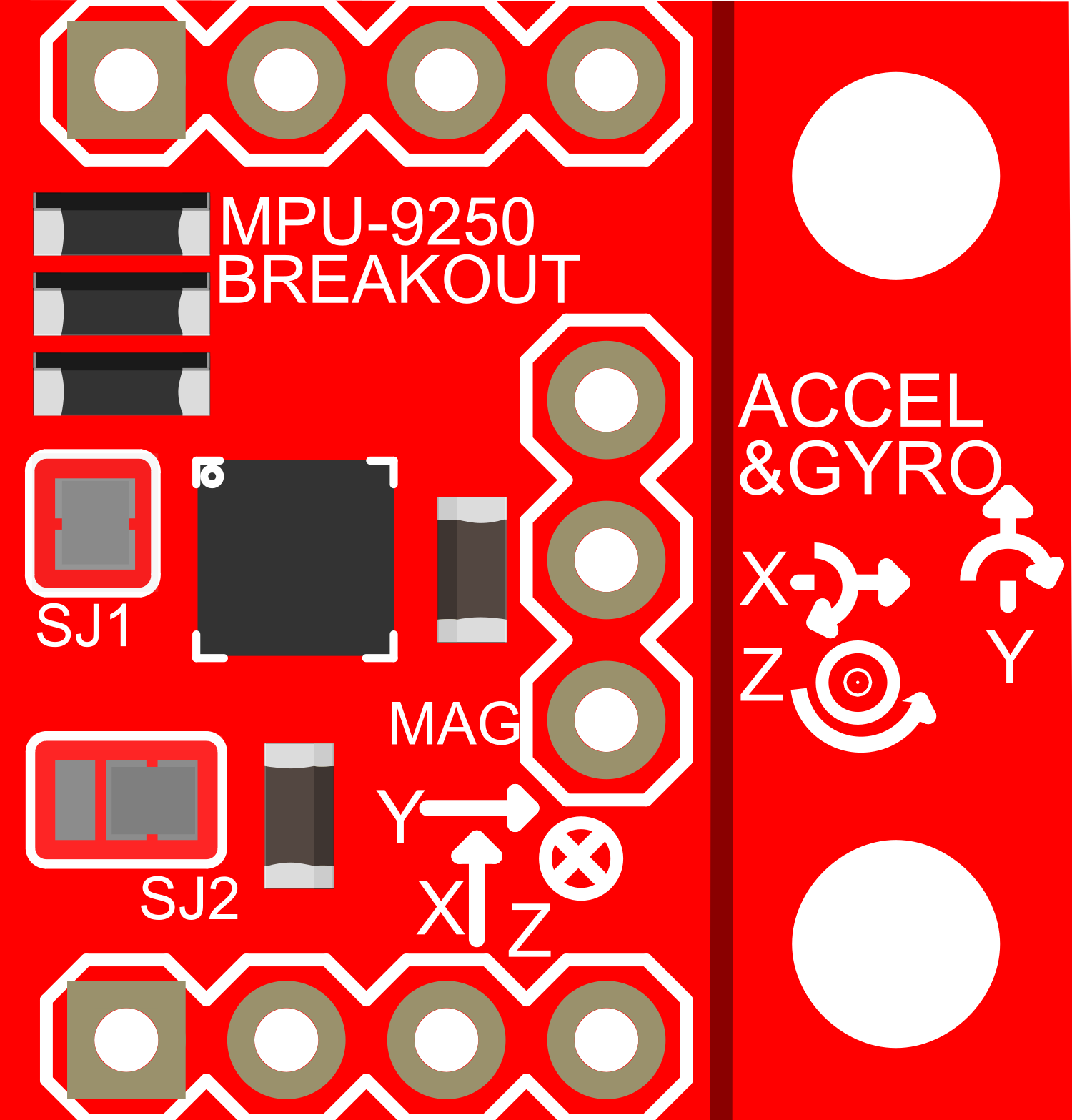
The SparkFun IMU Breakout - MPU-9250 is a compact, high-performance 9-axis motion tracking device that combines a 3-axis accelerometer, a 3-axis gyroscope, and a 3-axis magnetometer. This integrated sensor package is ideal for a wide range of applications, including robotics, drone flight control, virtual reality, and motion analysis. The MPU-9250 communicates via I2C or SPI, offering flexibility for various microcontroller interfaces.
Explore Projects Built with SparkFun IMU Breakout - MPU-9250

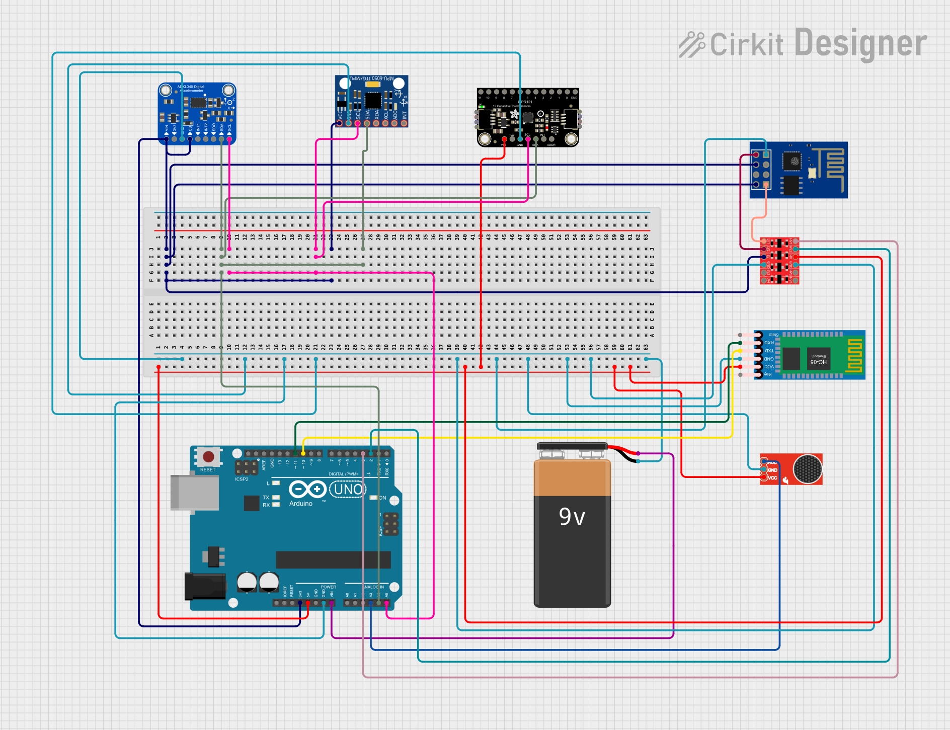
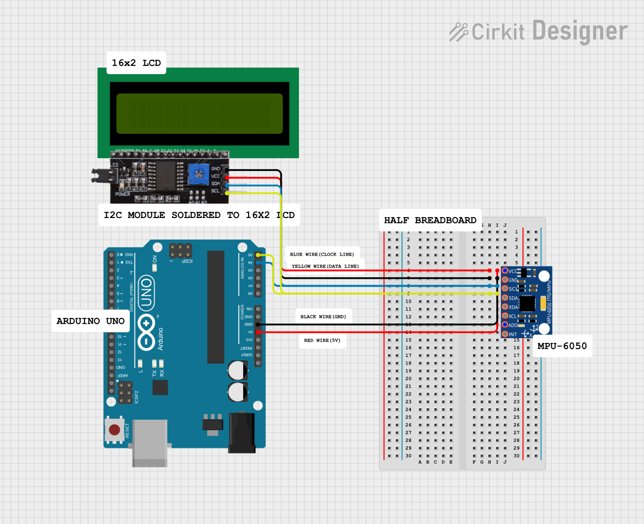
Explore Projects Built with SparkFun IMU Breakout - MPU-9250
Technical Specifications
Key Technical Details
- Supply Voltage (VDD): 2.4V - 3.6V
- Operating Current: 3.2mA
- Gyroscope Range: ±250, ±500, ±1000, ±2000 degrees/sec
- Accelerometer Range: ±2g, ±4g, ±8g, ±16g
- Magnetometer Range: ±4800µT
- Communication: I2C (up to 400kHz) and SPI (up to 1MHz)
- Operating Temperature Range: -40°C to +85°C
Pin Configuration and Descriptions
| Pin Number | Pin Name | Description |
|---|---|---|
| 1 | VDD | Power supply (2.4V - 3.6V) |
| 2 | GND | Ground connection |
| 3 | SDA/SDI | I2C Data Line / SPI Serial Data In |
| 4 | SCL/SCLK | I2C Clock Line / SPI Serial Clock |
| 5 | NCS | SPI Chip Select (Active Low) |
| 6 | INT | Interrupt Output |
| 7 | FSYNC | Frame Synchronization (Optional) |
| 8 | AD0/SDO | I2C Address Selection / SPI Serial Data Out |
Usage Instructions
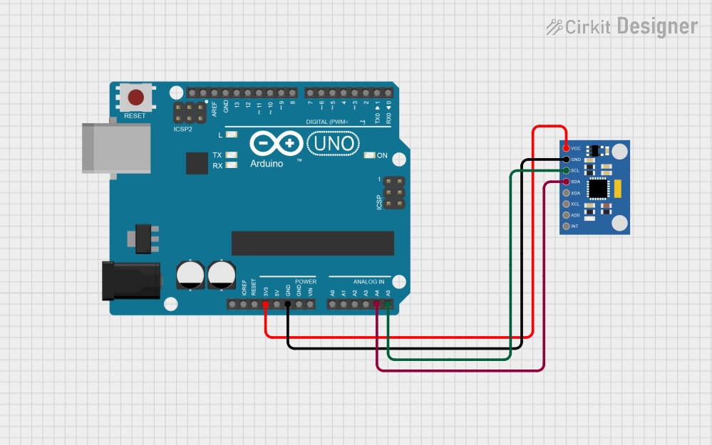
Integration with a Circuit
To use the MPU-9250 in a circuit:
- Connect VDD to a 2.4V - 3.6V power supply.
- Connect GND to the ground of your power supply.
- For I2C communication, connect SDA/SDI to your microcontroller's SDA line and SCL/SCLK to the SCL line.
- For SPI communication, connect SDA/SDI, SCL/SCLK, NCS, and AD0/SDO to the corresponding SPI pins on your microcontroller.
- Optionally, connect INT to an interrupt-capable pin on your microcontroller to use the interrupt feature.
- If using the FSYNC feature, connect it to a digital output on your microcontroller.
Important Considerations and Best Practices
- Ensure that the power supply is within the specified voltage range to prevent damage.
- Use pull-up resistors on the I2C lines if your microcontroller does not have built-in pull-ups.
- When using SPI, ensure that the NCS pin is pulled high to disable the device when not in use.
- For accurate readings, calibrate the magnetometer in the environment where it will be used.
- Avoid placing the MPU-9250 near magnetic fields that could interfere with the magnetometer.
Example Code for Arduino UNO
#include <Wire.h>
#include <MPU9250.h>

MPU9250 IMU(Wire, 0x68);
int status;

void setup() {
  Serial.begin(115200);
  while (!Serial) {} // Wait for serial port to connect

  status = IMU.begin();
  if (status < 0) {
    Serial.println("IMU initialization unsuccessful");
    Serial.println("Check IMU wiring or try cycling power");
    while (1) {}
  }
}

void loop() {
  if (IMU.readSensor() == 0) {
    Serial.print("AccelX: ");
    Serial.print(IMU.getAccelX_mss(), 6);
    Serial.print("\tGyroX: ");
    Serial.print(IMU.getGyroX_rads(), 6);
    Serial.print("\tMagX: ");
    Serial.print(IMU.getMagX_uT(), 6);
    Serial.println();
    // Add additional print statements for other axes as needed
  }
  delay(100);
}
Troubleshooting and FAQs
Common Issues
- No data or incorrect data: Ensure that the wiring is correct and that the correct communication protocol (I2C/SPI) is selected in your code.
- Inaccurate readings: Calibrate the sensor, especially the magnetometer, and ensure that there are no interfering magnetic fields.
- Device not recognized: Check the power supply and connections. Also, verify that the correct I2C address or SPI chip select is used.
Solutions and Tips for Troubleshooting
- Double-check all connections and solder joints.
- Use a logic analyzer or oscilloscope to verify communication signals.
- Reset the power to the MPU-9250 if it is unresponsive.
- Consult the MPU-9250 datasheet for detailed information on registers and configuration settings.
FAQs
Q: Can the MPU-9250 be used with a 5V microcontroller? A: Yes, but ensure that the power supply to the MPU-9250 is within the specified range and use logic level converters for communication lines.
Q: How do I change the I2C address of the MPU-9250? A: The I2C address can be changed by connecting the AD0/SDO pin to VDD or GND.
Q: What is the default I2C address of the MPU-9250? A: The default I2C address is 0x68 when AD0/SDO is connected to GND and 0x69 when connected to VDD.
Q: How can I verify that my MPU-9250 is functioning correctly? A: Run the example code provided and check the serial output for consistent and reasonable data readings.