How to Use SPEED MODE SWITCH: Examples, Pinouts, and Specs
Introduction
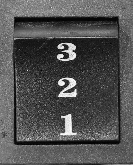
The SPEED MODE SWITCH is a versatile electronic component designed to allow users to select between multiple speed settings for a device. This switch is commonly used in applications where control over performance and energy consumption is critical. By toggling between predefined speed modes, users can optimize their devices for tasks requiring either high performance or energy efficiency.
Explore Projects Built with SPEED MODE SWITCH
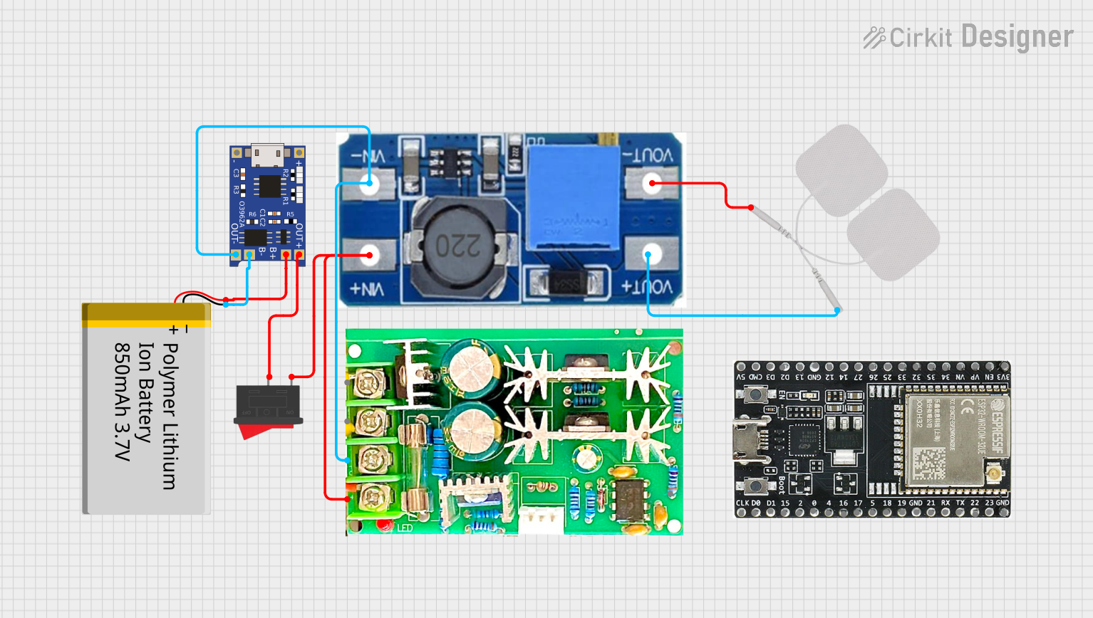
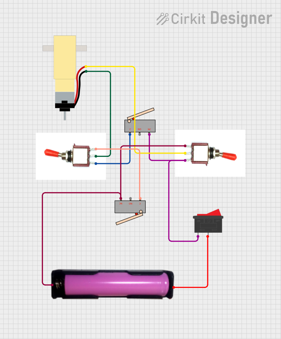
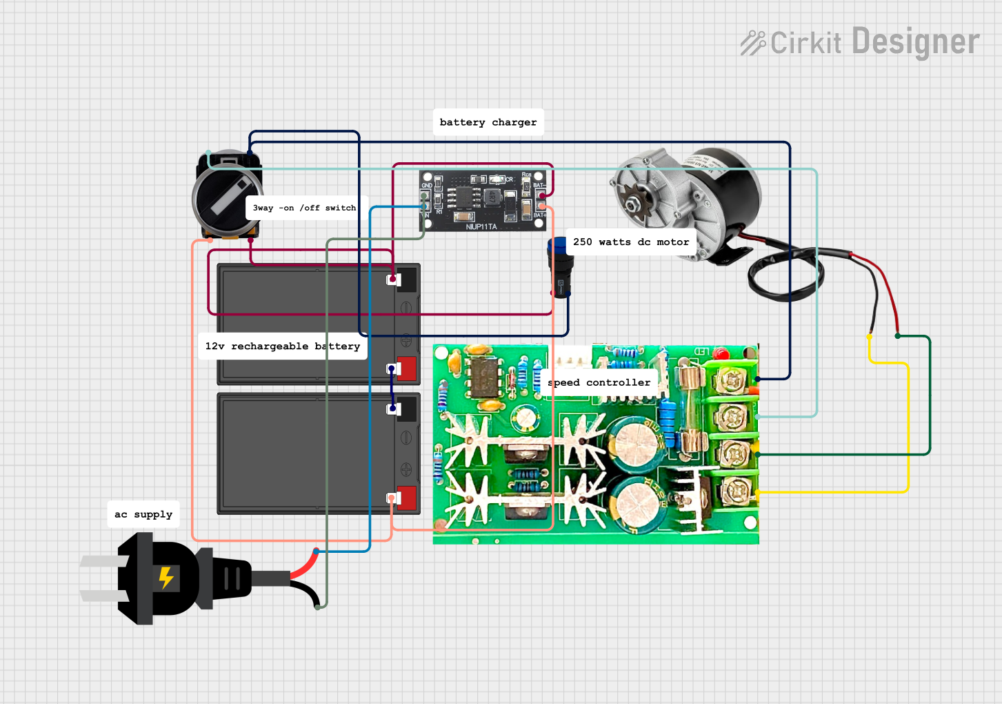

Explore Projects Built with SPEED MODE SWITCH
Common Applications and Use Cases
- Fan speed control in HVAC systems
- Motor speed selection in industrial equipment
- Speed adjustment in consumer electronics (e.g., blenders, drills)
- Power-saving modes in battery-operated devices
Technical Specifications
The SPEED MODE SWITCH is available in various configurations, such as rotary, slide, or toggle switches. Below are the general technical specifications:
| Parameter | Value |
|---|---|
| Operating Voltage | 3.3V to 24V |
| Maximum Current Rating | 2A |
| Contact Resistance | ≤ 50 mΩ |
| Insulation Resistance | ≥ 100 MΩ |
| Operating Temperature | -20°C to 85°C |
| Number of Positions | 2 to 5 (depending on the model) |
| Switch Type | SPDT, DPDT, or rotary |
Pin Configuration and Descriptions
The pin configuration varies depending on the type of SPEED MODE SWITCH. Below is an example for a 3-position SPDT (Single Pole Double Throw) switch:
| Pin | Description |
|---|---|
| Pin 1 | Common terminal (connected to the input voltage) |
| Pin 2 | Output terminal for Speed Mode 1 |
| Pin 3 | Output terminal for Speed Mode 2 |
For a rotary switch with 5 positions, the pin configuration may look like this:
| Pin | Description |
|---|---|
| Pin 1 | Common terminal (connected to the input voltage) |
| Pin 2 | Output terminal for Speed Mode 1 |
| Pin 3 | Output terminal for Speed Mode 2 |
| Pin 4 | Output terminal for Speed Mode 3 |
| Pin 5 | Output terminal for Speed Mode 4 |
| Pin 6 | Output terminal for Speed Mode 5 |
Usage Instructions
How to Use the SPEED MODE SWITCH in a Circuit
- Identify the Switch Type: Determine whether the switch is SPDT, DPDT, or rotary, and note the number of positions.
- Connect the Common Terminal: Connect the common terminal (Pin 1) to the input voltage or signal source.
- Connect the Output Terminals: Connect the output terminals (e.g., Pin 2, Pin 3) to the respective speed control inputs of your device.
- Secure the Switch: Mount the switch securely in your device's enclosure to ensure reliable operation.
- Test the Circuit: Verify that toggling the switch changes the speed settings as expected.
Important Considerations and Best Practices
- Voltage and Current Ratings: Ensure the switch's voltage and current ratings match your circuit requirements to avoid damage.
- Debouncing: Mechanical switches may produce noise or "bouncing" when toggled. Use a debouncing circuit or software to ensure stable operation.
- Wiring: Double-check all connections to avoid short circuits or incorrect speed settings.
- Mounting: Use appropriate mounting hardware to prevent accidental toggling or damage to the switch.
Example: Using the SPEED MODE SWITCH with an Arduino UNO
Below is an example of how to use a 3-position SPDT SPEED MODE SWITCH to control the speed of a motor via an Arduino UNO:
// Define pins for the SPEED MODE SWITCH
const int switchPin1 = 2; // Pin connected to Speed Mode 1
const int switchPin2 = 3; // Pin connected to Speed Mode 2
const int motorPin = 9;   // PWM pin connected to the motor

void setup() {
  // Set switch pins as inputs
  pinMode(switchPin1, INPUT_PULLUP);
  pinMode(switchPin2, INPUT_PULLUP);

  // Set motor pin as output
  pinMode(motorPin, OUTPUT);
}

void loop() {
  // Read the state of the switch pins
  bool mode1 = digitalRead(switchPin1) == LOW; // LOW means switch is active
  bool mode2 = digitalRead(switchPin2) == LOW;

  // Control motor speed based on switch position
  if (mode1) {
    analogWrite(motorPin, 128); // Set motor to medium speed (50% duty cycle)
  } else if (mode2) {
    analogWrite(motorPin, 255); // Set motor to high speed (100% duty cycle)
  } else {
    analogWrite(motorPin, 0);   // Turn off the motor
  }
}
Notes:
- Use
INPUT_PULLUPto avoid the need for external pull-up resistors. - Adjust the
analogWritevalues to match your motor's speed requirements.
Troubleshooting and FAQs
Common Issues and Solutions
Switch Does Not Change Speed Settings
- Cause: Incorrect wiring or loose connections.
- Solution: Verify all connections and ensure the common terminal is properly connected.
Device Operates Erratically
- Cause: Switch bouncing or noise.
- Solution: Add a debouncing circuit or implement software debouncing in your microcontroller code.
Switch Feels Stiff or Unresponsive
- Cause: Mechanical wear or debris inside the switch.
- Solution: Clean the switch contacts or replace the switch if necessary.
Overheating or Damage
- Cause: Exceeding the switch's voltage or current ratings.
- Solution: Use a switch with appropriate ratings for your application.
FAQs
Q: Can I use the SPEED MODE SWITCH for AC devices?
A: Yes, but ensure the switch is rated for AC voltage and current. For high-power AC devices, consider using a relay in conjunction with the switch.
Q: How do I add more speed modes?
A: Use a rotary switch with additional positions or combine multiple switches to achieve more speed settings.
Q: Can I use this switch with a microcontroller other than Arduino?
A: Yes, the switch can be used with any microcontroller that supports digital input pins. Adjust the code accordingly for your platform.
Q: What is the lifespan of the SPEED MODE SWITCH?
A: The typical lifespan is 10,000 to 100,000 cycles, depending on the model and operating conditions.