How to Use Voltage Sensor DC 25V: Examples, Pinouts, and Specs
Introduction
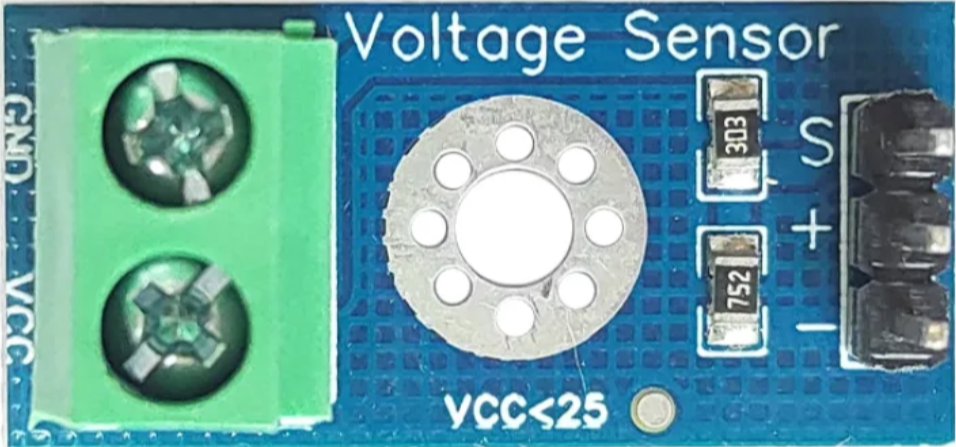
The Voltage Sensor DC 25V is a device designed to measure and monitor the voltage level in a DC circuit up to 25 volts. This sensor is commonly used in various applications, including battery monitoring, power supply testing, and voltage regulation systems. It provides an easy and efficient way to measure voltage levels and can be interfaced with microcontrollers like the Arduino UNO for real-time monitoring and data logging.
Explore Projects Built with Voltage Sensor DC 25V
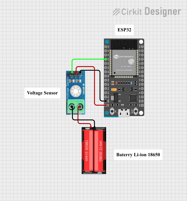
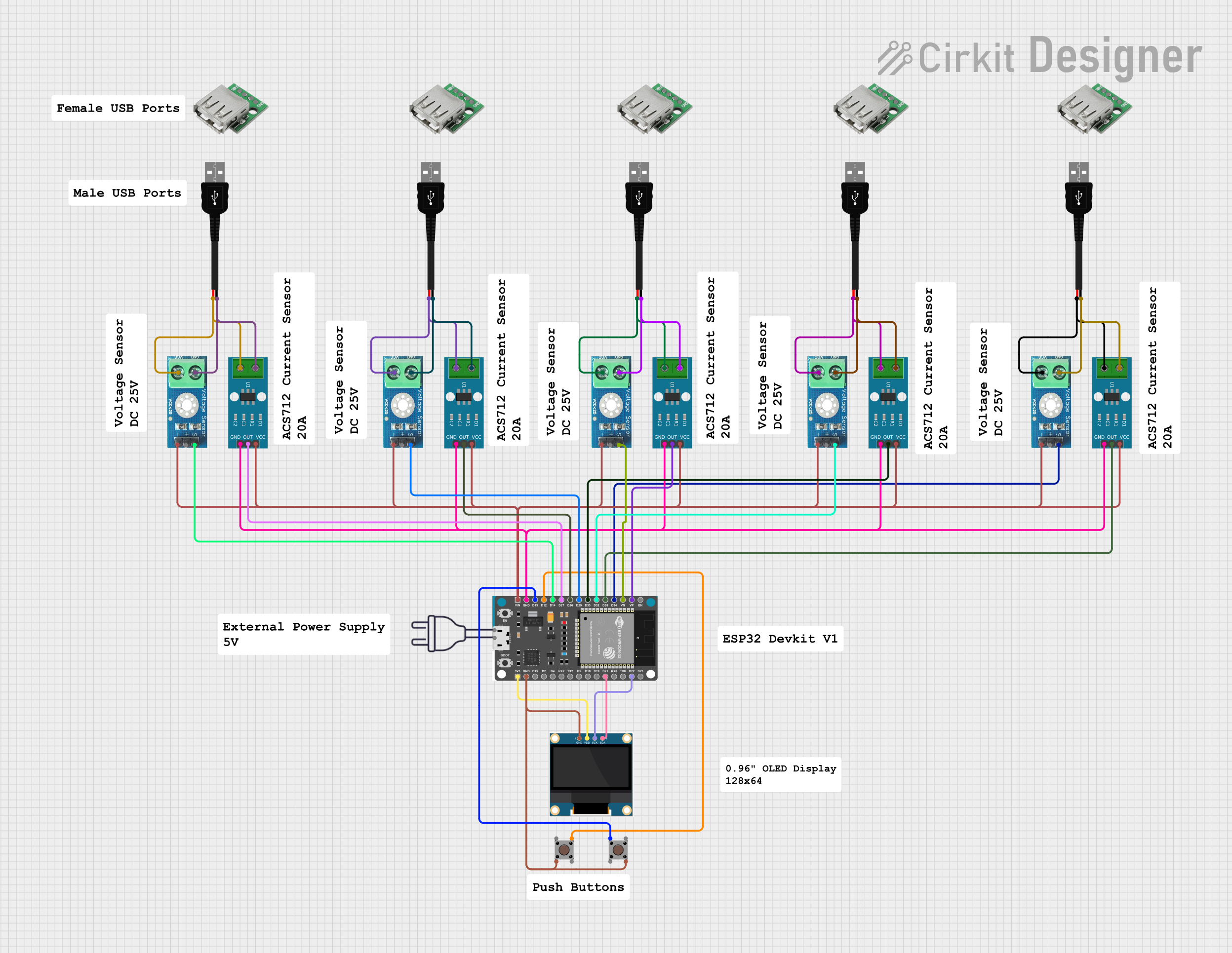
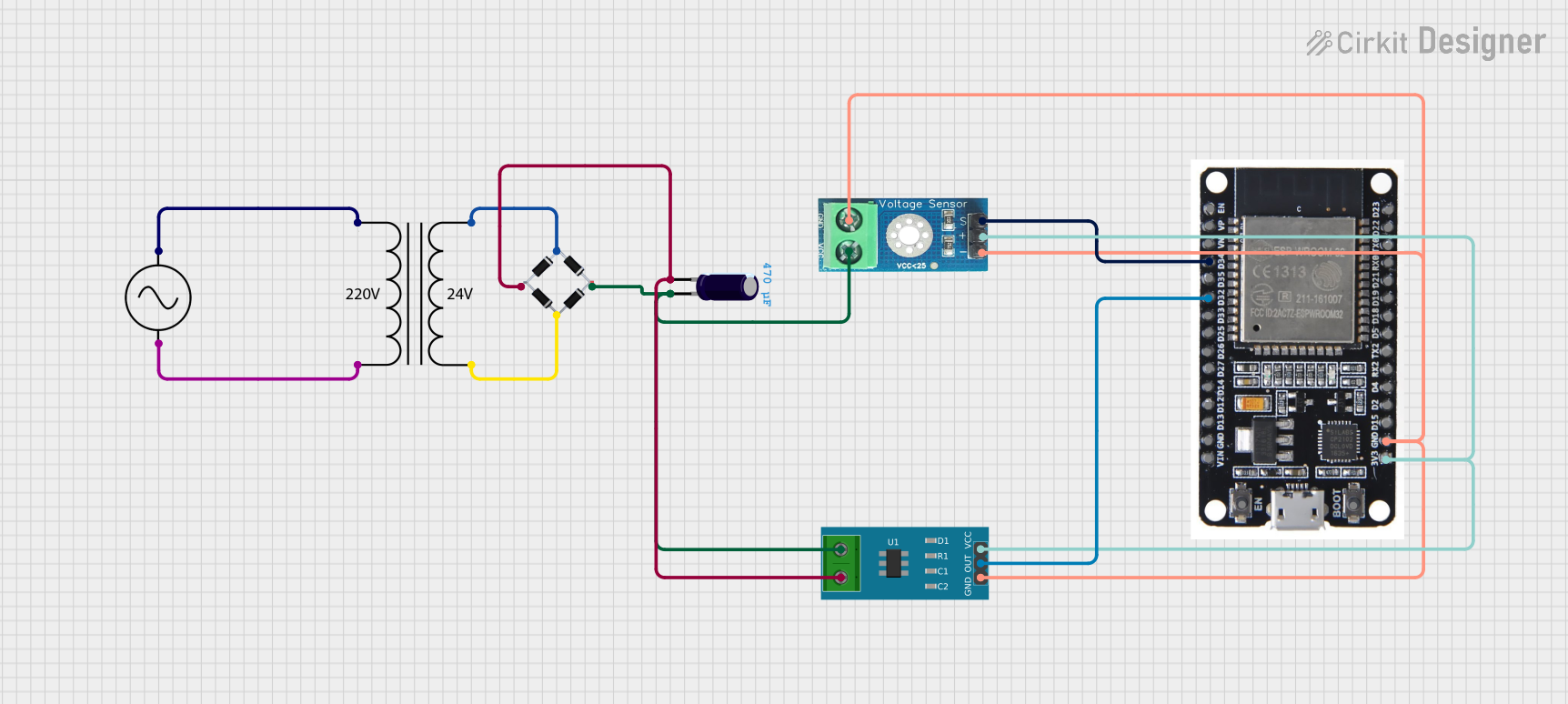
Explore Projects Built with Voltage Sensor DC 25V
Technical Specifications
Key Technical Details
| Parameter | Value |
|---|---|
| Input Voltage Range | 0 - 25V DC |
| Output Voltage | 0 - 5V DC |
| Measurement Accuracy | ±1% |
| Operating Temperature | -40°C to 85°C |
| Dimensions | 30mm x 20mm x 10mm |
Pin Configuration and Descriptions
| Pin Number | Pin Name | Description |
|---|---|---|
| 1 | VCC | Power supply (typically 5V) |
| 2 | GND | Ground |
| 3 | VIN+ | Positive voltage input (0-25V DC) |
| 4 | VIN- | Negative voltage input (typically GND) |
| 5 | VOUT | Analog voltage output (0-5V DC) |
Usage Instructions
How to Use the Component in a Circuit
- Power Supply Connection: Connect the VCC pin to a 5V power supply and the GND pin to the ground of the power supply.
- Voltage Measurement Connection: Connect the VIN+ pin to the positive terminal of the voltage source you want to measure and the VIN- pin to the ground of the voltage source.
- Output Connection: Connect the VOUT pin to an analog input pin of a microcontroller (e.g., Arduino UNO) to read the voltage level.
Important Considerations and Best Practices
- Voltage Range: Ensure that the input voltage does not exceed 25V DC to avoid damaging the sensor.
- Calibration: For accurate measurements, calibrate the sensor by comparing its output with a known reference voltage.
- Noise Reduction: Use proper decoupling capacitors to reduce noise and improve measurement accuracy.
- Temperature Effects: Be aware of the operating temperature range and avoid exposing the sensor to extreme temperatures.
Example Code for Arduino UNO
// Voltage Sensor DC 25V Example Code for Arduino UNO

const int sensorPin = A0; // Analog input pin that the sensor is attached to
float voltage = 0.0;      // Variable to store the voltage value

void setup() {
  Serial.begin(9600); // Initialize serial communication at 9600 baud rate
}

void loop() {
  int sensorValue = analogRead(sensorPin); // Read the analog input
  voltage = sensorValue * (5.0 / 1023.0) * (25.0 / 5.0);
  // Convert the analog reading to voltage
  // 5.0/1023.0 converts the analog value to a voltage (0-5V)
  // 25.0/5.0 scales the voltage to the input range (0-25V)

  Serial.print("Voltage: ");
  Serial.print(voltage);
  Serial.println(" V");

  delay(1000); // Wait for 1 second before taking another reading
}
Troubleshooting and FAQs
Common Issues Users Might Face
Incorrect Voltage Readings:
- Solution: Ensure that the sensor is properly calibrated. Check the connections and make sure the input voltage does not exceed 25V DC.
No Output Signal:
- Solution: Verify that the sensor is powered correctly. Check the VCC and GND connections. Ensure that the VIN+ and VIN- pins are connected to the voltage source.
Fluctuating Readings:
- Solution: Use decoupling capacitors to filter out noise. Ensure stable power supply and proper grounding.
FAQs
Q1: Can I use this sensor to measure AC voltage?
- A1: No, this sensor is designed for DC voltage measurement only. Using it to measure AC voltage can damage the sensor.
Q2: How do I calibrate the sensor?
- A2: To calibrate the sensor, compare its output with a known reference voltage and adjust the scaling factor in the code accordingly.
Q3: What is the maximum input voltage for this sensor?
- A3: The maximum input voltage is 25V DC. Exceeding this limit can damage the sensor.
Q4: Can I use this sensor with other microcontrollers?
- A4: Yes, you can use this sensor with other microcontrollers that have analog input pins, such as ESP8266, ESP32, and others.
By following this documentation, users can effectively utilize the Voltage Sensor DC 25V in their projects, ensuring accurate voltage measurements and reliable performance.