How to Use RS 485: Examples, Pinouts, and Specs
Introduction
RS-485 is a standard for serial communication that enables reliable, long-distance data transmission over twisted-pair cables. It supports multiple devices on a single bus, making it ideal for multi-point communication systems. RS-485 is widely used in industrial automation, building management systems, and other applications where robust communication is required in electrically noisy environments.
Explore Projects Built with RS 485


Explore Projects Built with RS 485
Common Applications:
- Industrial automation and control systems
- Building management systems (e.g., HVAC, lighting control)
- Data acquisition systems
- Security and surveillance systems
- Point-of-sale (POS) systems
- Communication between microcontrollers and sensors over long distances
Technical Specifications
Below are the key technical details and pin configuration for RS-485 transceivers:
Key Technical Details:
- Communication Standard: RS-485 (TIA/EIA-485)
- Maximum Data Rate: Up to 10 Mbps (depending on cable length)
- Maximum Cable Length: 1200 meters (at lower data rates)
- Number of Devices: Up to 32 drivers and 32 receivers on a single bus
- Voltage Levels: Differential signaling, typically ±5V
- Noise Immunity: High, due to differential signaling
- Termination Resistor: Typically 120 ohms at each end of the bus
- Connector Type: Often uses screw terminals or DB9 connectors
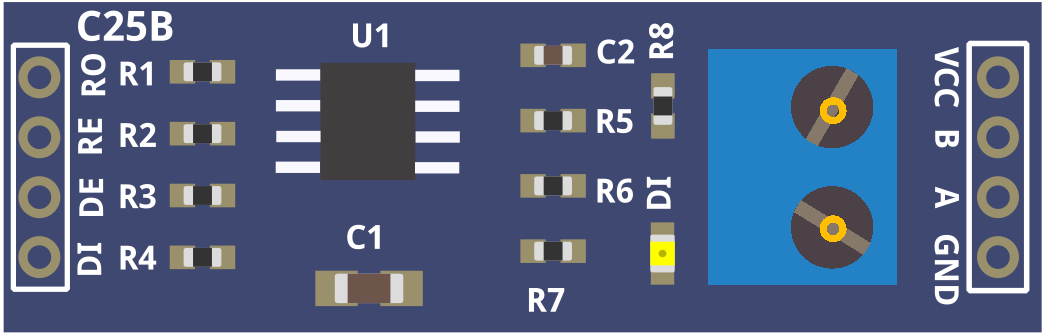
Pin Configuration and Descriptions:
The RS-485 transceiver typically has the following pins:
| Pin Name | Description |
|---|---|
| A (D+) | Non-inverting differential signal line (positive data line) |
| B (D-) | Inverting differential signal line (negative data line) |
| GND | Ground reference for the communication system |
| VCC | Power supply input for the transceiver (commonly 3.3V or 5V) |
| DE | Driver Enable: Activates the driver for transmitting data |
| RE | Receiver Enable: Activates the receiver for receiving data |
| DI | Data Input: Input data to be transmitted (connected to the microcontroller) |
| RO | Receiver Output: Output data received from the bus (connected to the microcontroller) |
Usage Instructions
How to Use RS-485 in a Circuit:
- Connect the Power Supply: Provide the appropriate voltage (e.g., 3.3V or 5V) to the VCC pin and connect the GND pin to the ground of your circuit.
- Connect the Differential Lines:
- Connect the A (D+) and B (D-) lines to the twisted-pair cable for communication.
- Ensure proper polarity when connecting multiple devices on the bus.
- Enable the Driver and Receiver:
- Use the DE pin to enable the driver for transmitting data.
- Use the RE pin to enable the receiver for receiving data. These pins can often be tied together for simplicity.
- Termination Resistors:
- Place a 120-ohm resistor at each end of the RS-485 bus to match the cable impedance and prevent signal reflections.
- Connect to a Microcontroller:
- Connect the DI pin to the microcontroller's TX (transmit) pin.
- Connect the RO pin to the microcontroller's RX (receive) pin.
Important Considerations:
- Bus Topology: Use a daisy-chain topology for connecting devices. Avoid star or ring topologies to prevent signal integrity issues.
- Grounding: Ensure all devices share a common ground to avoid communication errors.
- Cable Selection: Use twisted-pair cables with proper shielding for long-distance communication.
- Baud Rate vs. Distance: Higher baud rates reduce the maximum communication distance. Choose a baud rate suitable for your application.
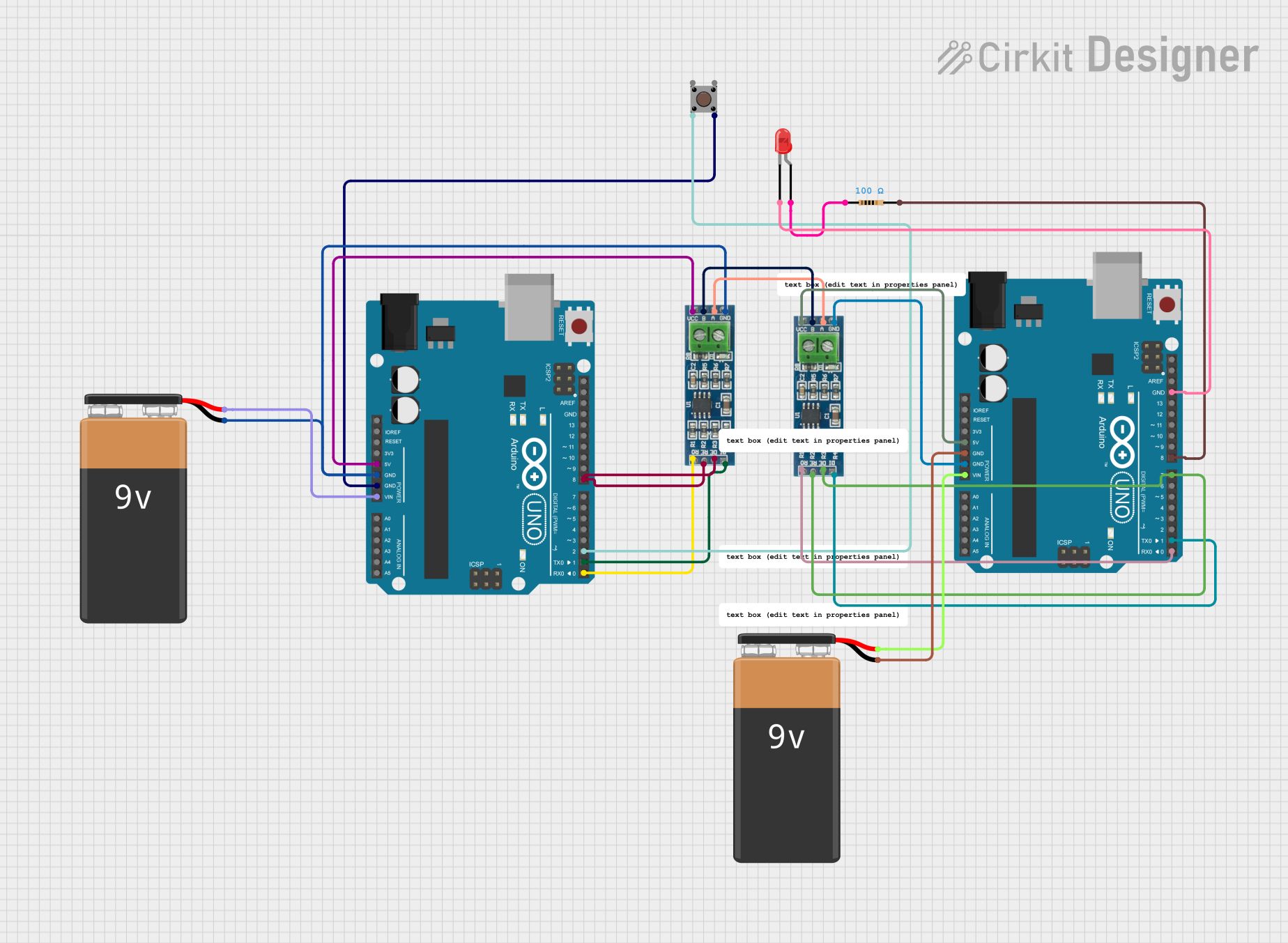
Example: RS-485 with Arduino UNO
Below is an example of using an RS-485 module with an Arduino UNO to send and receive data:
Transmitter Code:
// RS-485 Transmitter Example
#include <SoftwareSerial.h>

// Define RS-485 pins
#define DE_PIN 2  // Driver Enable pin
#define RE_PIN 3  // Receiver Enable pin
#define TX_PIN 4  // Transmit pin
#define RX_PIN 5  // Receive pin

// Initialize SoftwareSerial for RS-485 communication
SoftwareSerial RS485Serial(TX_PIN, RX_PIN);

void setup() {
  pinMode(DE_PIN, OUTPUT);
  pinMode(RE_PIN, OUTPUT);

  // Set DE and RE to HIGH to enable transmission
  digitalWrite(DE_PIN, HIGH);
  digitalWrite(RE_PIN, HIGH);

  RS485Serial.begin(9600); // Set baud rate
}

void loop() {
  RS485Serial.println("Hello from RS-485 Transmitter!");
  delay(1000); // Send data every second
}
Receiver Code:
// RS-485 Receiver Example
#include <SoftwareSerial.h>

// Define RS-485 pins
#define DE_PIN 2  // Driver Enable pin
#define RE_PIN 3  // Receiver Enable pin
#define TX_PIN 4  // Transmit pin
#define RX_PIN 5  // Receive pin

// Initialize SoftwareSerial for RS-485 communication
SoftwareSerial RS485Serial(TX_PIN, RX_PIN);

void setup() {
  pinMode(DE_PIN, OUTPUT);
  pinMode(RE_PIN, OUTPUT);

  // Set DE to LOW and RE to LOW to enable reception
  digitalWrite(DE_PIN, LOW);
  digitalWrite(RE_PIN, LOW);

  RS485Serial.begin(9600); // Set baud rate
  Serial.begin(9600);      // For debugging via Serial Monitor
}

void loop() {
  if (RS485Serial.available()) {
    String receivedData = RS485Serial.readString();
    Serial.println("Received: " + receivedData); // Print received data
  }
}
Troubleshooting and FAQs
Common Issues:
No Communication Between Devices:
- Check the wiring of the A (D+) and B (D-) lines. Ensure proper polarity.
- Verify that the DE and RE pins are correctly configured for transmission and reception.
- Ensure the baud rate matches on all devices.
Data Corruption:
- Check for proper termination resistors (120 ohms) at both ends of the bus.
- Use shielded twisted-pair cables to reduce noise interference.
Limited Communication Range:
- Reduce the baud rate to increase the maximum communication distance.
- Ensure the cable length does not exceed 1200 meters.
Multiple Devices Not Communicating:
- Verify that the RS-485 bus is properly terminated.
- Ensure all devices share a common ground.
FAQs:
Q: Can RS-485 support full-duplex communication?
A: RS-485 is primarily designed for half-duplex communication. However, full-duplex communication can be achieved using two separate RS-485 buses.
Q: How many devices can I connect to an RS-485 bus?
A: RS-485 supports up to 32 drivers and 32 receivers on a single bus. Some modern transceivers allow for even more devices.
Q: Do I need termination resistors for short-distance communication?
A: Termination resistors are generally not required for very short distances, but they are recommended for longer cables to prevent signal reflections.
Q: Can I use RS-485 for wireless communication?
A: RS-485 is a wired communication standard. For wireless communication, you would need additional hardware like RF modules.