How to Use OV5640 Breakout Board: Examples, Pinouts, and Specs
Introduction
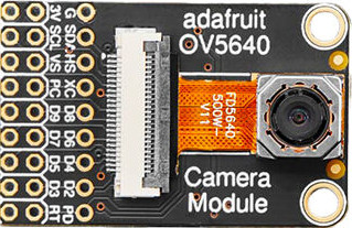
The OV5640 Breakout Board by Adafruit is a compact circuit board featuring the OV5640 image sensor. This sensor is capable of capturing high-resolution images and streaming video, making it ideal for a wide range of applications. The breakout board simplifies integration into projects by providing easy access to the sensor's functionality through a user-friendly pinout.
Explore Projects Built with OV5640 Breakout Board
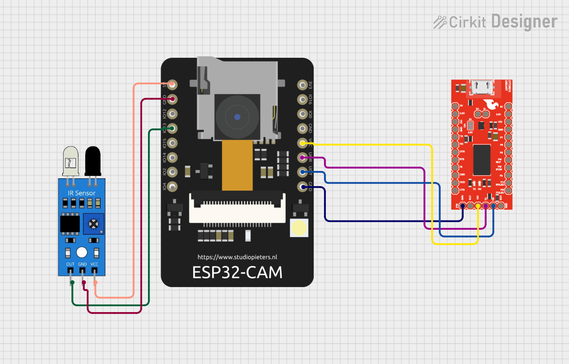
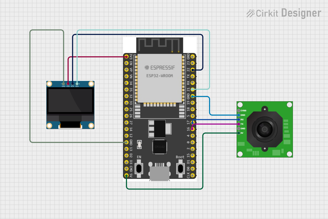

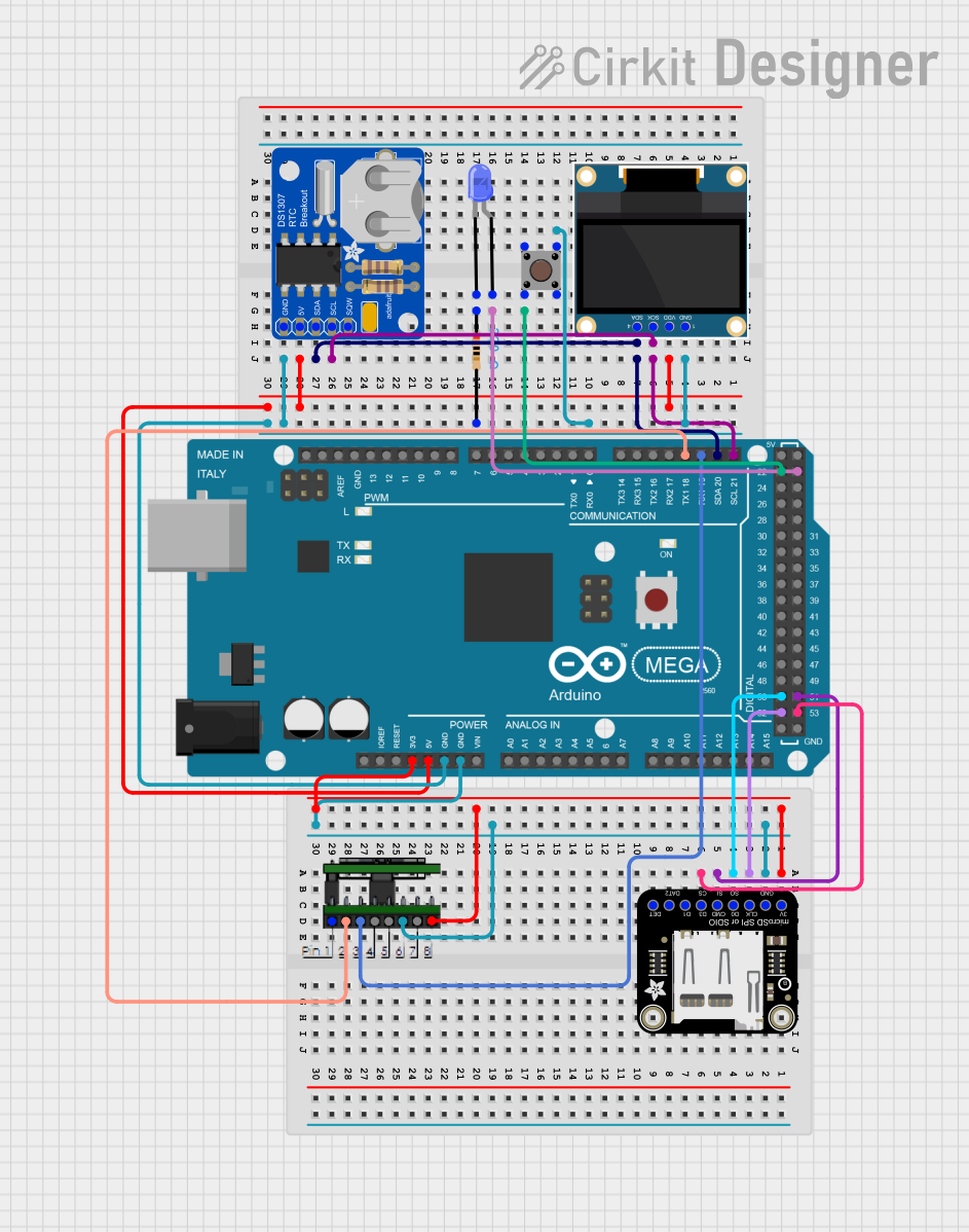
Explore Projects Built with OV5640 Breakout Board
Common Applications and Use Cases
- Embedded Vision Systems: Ideal for robotics, drones, and IoT devices requiring visual input.
- Surveillance and Security: Used in security cameras for high-quality image capture.
- Machine Learning Projects: Suitable for image recognition and object detection tasks.
- DIY Electronics: Perfect for hobbyists building custom cameras or video systems.
Technical Specifications
The OV5640 Breakout Board is designed to provide high performance in a compact form factor. Below are the key technical details:
Key Technical Details
- Image Sensor: OV5640 CMOS sensor
- Resolution: Up to 5 megapixels (2592 x 1944)
- Video Output: 1080p at 30 fps, 720p at 60 fps
- Lens: Fixed focus
- Interface: DVP (Digital Video Port) and I2C for configuration
- Operating Voltage: 3.3V (logic level)
- Power Consumption: ~140 mW (active mode)
- Dimensions: 25mm x 24mm (approx.)
Pin Configuration and Descriptions
The breakout board features a set of pins for easy interfacing. Below is the pinout:
| Pin Name | Type | Description |
|---|---|---|
3.3V |
Power Input | 3.3V power supply input for the breakout board. |
GND |
Ground | Ground connection. |
SCL |
I2C Clock | Serial clock line for I2C communication. |
SDA |
I2C Data | Serial data line for I2C communication. |
VSYNC |
Output | Vertical synchronization signal for video output. |
HREF |
Output | Horizontal reference signal for video output. |
PCLK |
Output | Pixel clock signal for synchronizing data transfer. |
D0-D7 |
Output | 8-bit parallel data output for image data. |
RESET |
Input | Active-low reset pin to reset the sensor. |
PWDN |
Input | Power-down pin to place the sensor in low-power mode. |
XCLK |
Input | External clock input for driving the sensor (typically 24 MHz). |
Usage Instructions
The OV5640 Breakout Board is straightforward to use in a variety of projects. Below are the steps and best practices for integrating it into your circuit.
How to Use the Component in a Circuit
- Power the Board: Connect the
3.3Vpin to a 3.3V power source and theGNDpin to ground. - Connect I2C Lines: Use the
SCLandSDApins to communicate with the sensor via I2C. Ensure pull-up resistors (typically 4.7kΩ) are used on these lines. - Connect Video Output: Use the
D0-D7pins for parallel data output, along withVSYNC,HREF, andPCLKfor synchronization. - Provide an External Clock: Connect a 24 MHz clock signal to the
XCLKpin to drive the sensor. - Optional Control Pins: Use the
RESETpin to reset the sensor and thePWDNpin to enable low-power mode if needed.
Important Considerations and Best Practices
- Voltage Levels: Ensure all logic signals are at 3.3V levels to avoid damaging the sensor.
- Clock Stability: Use a stable 24 MHz clock source for optimal performance.
- Lens Adjustment: The fixed-focus lens may need to be manually adjusted for specific applications.
- I2C Address: The default I2C address of the OV5640 is
0x78. Ensure no conflicts with other devices on the I2C bus.
Example: Connecting to an Arduino UNO
The OV5640 can be connected to an Arduino UNO for basic configuration and control. Below is an example code snippet to initialize the sensor via I2C:
#include <Wire.h>

// OV5640 I2C address
#define OV5640_I2C_ADDR 0x78

void setup() {
  Wire.begin(); // Initialize I2C communication
  Serial.begin(9600); // Initialize serial communication for debugging

  // Reset the OV5640
  Wire.beginTransmission(OV5640_I2C_ADDR);
  Wire.write(0x3008); // System control register
  Wire.write(0x82);   // Reset command
  Wire.endTransmission();
  delay(100); // Wait for the sensor to reset

  Serial.println("OV5640 initialized.");
}

void loop() {
  // Add your code to capture images or configure the sensor
}
Notes:
- The above code demonstrates basic initialization. For full functionality, additional configuration registers must be set based on your application.
- Use a logic level shifter if connecting to a 5V microcontroller like the Arduino UNO.
Troubleshooting and FAQs
Common Issues and Solutions
No Image Output:
- Ensure the
XCLKpin is receiving a stable 24 MHz clock signal. - Verify that the
3.3VandGNDconnections are secure. - Check the I2C communication lines (
SCLandSDA) for proper pull-up resistors.
- Ensure the
I2C Communication Fails:
- Confirm the I2C address (
0x78) matches the sensor's default address. - Check for conflicts with other devices on the I2C bus.
- Ensure the I2C lines are not too long, as this can cause signal degradation.
- Confirm the I2C address (
Blurry or Out-of-Focus Images:
- Adjust the fixed-focus lens manually to achieve the desired focus.
- Ensure the sensor is clean and free of dust or smudges.
High Power Consumption:
- Use the
PWDNpin to place the sensor in low-power mode when not in use. - Minimize active time by capturing images only when necessary.
- Use the
FAQs
Can the OV5640 capture video? Yes, the OV5640 supports video output at resolutions up to 1080p at 30 fps.
What is the maximum resolution of the OV5640? The sensor supports up to 5 megapixels (2592 x 1944).
Can I use the OV5640 with a Raspberry Pi? Yes, the OV5640 can be interfaced with a Raspberry Pi using the I2C and DVP interfaces, but additional software configuration may be required.
Is the OV5640 compatible with 5V logic? No, the OV5640 operates at 3.3V logic levels. Use a level shifter if interfacing with 5V systems.
By following this documentation, you can successfully integrate the OV5640 Breakout Board into your projects and troubleshoot common issues effectively.