How to Use INA226 V/I Sensor: Examples, Pinouts, and Specs
Introduction
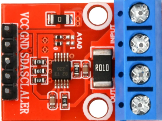
The INA226 is a high-side current shunt monitor with an integrated I2C interface, designed for precise voltage, current, and power measurements. It features a built-in 16-bit analog-to-digital converter (ADC) and programmable gain, making it highly versatile for power monitoring applications. The INA226 is widely used in systems requiring accurate power management, such as battery-operated devices, power supplies, and industrial equipment.
Explore Projects Built with INA226 V/I Sensor

Explore Projects Built with INA226 V/I Sensor
Common Applications
- Battery management systems
- Power supply monitoring
- Energy metering
- Industrial automation
- IoT devices requiring power optimization
Technical Specifications
The INA226 offers a range of features and specifications that make it suitable for high-precision power monitoring. Below are the key technical details:
Key Specifications
| Parameter | Value |
|---|---|
| Supply Voltage (Vcc) | 2.7V to 5.5V |
| Input Voltage Range | 0V to 36V |
| Current Measurement Range | Determined by external shunt resistor |
| ADC Resolution | 16-bit |
| Communication Interface | I2C (up to 1 MHz) |
| Operating Temperature | -40°C to +125°C |
| Power Consumption | 310 µA (typical) |
Pin Configuration
The INA226 is available in an 8-pin package. Below is the pinout and description:
| Pin No. | Pin Name | Description |
|---|---|---|
| 1 | V+ | Positive supply voltage (2.7V to 5.5V) |
| 2 | IN+ | Positive input for current shunt voltage |
| 3 | IN- | Negative input for current shunt voltage |
| 4 | GND | Ground |
| 5 | SCL | I2C clock line |
| 6 | SDA | I2C data line |
| 7 | ALERT | Alert output (programmable) |
| 8 | ADDR | I2C address selection |
Usage Instructions
The INA226 is straightforward to use in a circuit, but proper configuration and calibration are essential for accurate measurements. Below are the steps and considerations for using the INA226:
Circuit Connection
- Power Supply: Connect the V+ pin to a 2.7V to 5.5V power source and the GND pin to ground.
- Shunt Resistor: Place a precision shunt resistor between the IN+ and IN- pins to measure current. The value of the resistor determines the current measurement range.
- Voltage Measurement: Connect the IN+ pin to the high-side voltage of the load and the IN- pin to the low-side.
- I2C Interface: Connect the SCL and SDA pins to the corresponding I2C lines of your microcontroller. Use pull-up resistors (typically 4.7 kΩ) on these lines.
- Address Selection: Use the ADDR pin to set the I2C address by connecting it to GND, V+, or leaving it floating.
Arduino UNO Example Code
Below is an example of how to interface the INA226 with an Arduino UNO to measure current and voltage:
#include <Wire.h>

// INA226 I2C address (default: 0x40)
#define INA226_ADDRESS 0x40

// INA226 register addresses
#define REG_CONFIG 0x00
#define REG_SHUNT_VOLTAGE 0x01
#define REG_BUS_VOLTAGE 0x02

void setup() {
  Wire.begin(); // Initialize I2C communication
  Serial.begin(9600); // Initialize serial communication for debugging

  // Configure the INA226
  Wire.beginTransmission(INA226_ADDRESS);
  Wire.write(REG_CONFIG); // Point to the configuration register
  Wire.write(0x45); // MSB: Set averaging and conversion times
  Wire.write(0x27); // LSB: Enable shunt and bus voltage measurements
  Wire.endTransmission();
}

void loop() {
  float shuntVoltage = readRegister(REG_SHUNT_VOLTAGE) * 0.0025; // Convert to mV
  float busVoltage = readRegister(REG_BUS_VOLTAGE) * 0.00125; // Convert to V

  // Calculate current (I = Vshunt / Rshunt)
  float shuntResistor = 0.1; // Example: 0.1 ohm shunt resistor
  float current = shuntVoltage / shuntResistor;

  // Print results
  Serial.print("Bus Voltage: ");
  Serial.print(busVoltage);
  Serial.println(" V");

  Serial.print("Shunt Voltage: ");
  Serial.print(shuntVoltage);
  Serial.println(" mV");

  Serial.print("Current: ");
  Serial.print(current);
  Serial.println(" A");

  delay(1000); // Wait 1 second before the next reading
}

// Function to read a 16-bit register from the INA226
uint16_t readRegister(uint8_t reg) {
  Wire.beginTransmission(INA226_ADDRESS);
  Wire.write(reg); // Point to the desired register
  Wire.endTransmission();

  Wire.requestFrom(INA226_ADDRESS, 2); // Request 2 bytes
  while (Wire.available() < 2); // Wait for data

  uint16_t value = Wire.read() << 8; // Read MSB
  value |= Wire.read(); // Read LSB
  return value;
}
Important Considerations
- Shunt Resistor Selection: Choose a shunt resistor with low tolerance (e.g., 0.1% or better) for accurate current measurements.
- I2C Pull-Up Resistors: Ensure proper pull-up resistors are used on the I2C lines to avoid communication issues.
- Calibration: Calibrate the INA226 for your specific shunt resistor value using the calibration register (not covered in this example).
- Alert Pin: Use the ALERT pin for overcurrent or undervoltage warnings by configuring the alert limits.
Troubleshooting and FAQs
Common Issues
No I2C Communication:
- Ensure the correct I2C address is used.
- Verify pull-up resistors are connected to the SDA and SCL lines.
- Check for loose or incorrect wiring.
Incorrect Current or Voltage Readings:
- Verify the shunt resistor value and connections.
- Ensure proper calibration of the INA226.
- Check for noise or interference in the circuit.
Alert Pin Not Functioning:
- Confirm the alert limits are correctly configured in the INA226 registers.
- Verify the ALERT pin is properly connected to the microcontroller.
FAQs
Q: Can the INA226 measure negative currents?
A: No, the INA226 is designed for high-side current sensing and cannot measure negative currents.
Q: What is the maximum current the INA226 can measure?
A: The maximum current depends on the value of the shunt resistor and the maximum measurable shunt voltage (±81.92 mV).
Q: Can I use the INA226 with a 3.3V microcontroller?
A: Yes, the INA226 operates with supply voltages from 2.7V to 5.5V, making it compatible with 3.3V systems.
Q: How do I set a custom I2C address?
A: Use the ADDR pin to select one of the available I2C addresses by connecting it to GND, V+, or leaving it floating.
By following this documentation, you can effectively integrate the INA226 into your projects for precise voltage, current, and power monitoring.