How to Use CB Connector 8 pin (male): Examples, Pinouts, and Specs
Introduction
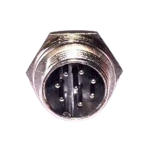
The CB Connector 8 Pin (Male) is a versatile and reliable electronic component designed for connecting various devices and circuits. With its 8-pin configuration, it provides a secure interface for both signal and power transmission, ensuring stable and efficient operation in a wide range of applications. This connector is commonly used in industrial equipment, consumer electronics, and prototyping projects.
Explore Projects Built with CB Connector 8 pin (male)


Explore Projects Built with CB Connector 8 pin (male)
Common Applications and Use Cases
- Signal and power connections in industrial control systems
- Interfacing between PCBs (Printed Circuit Boards)
- Prototyping and development of electronic circuits
- Audio, video, and data transmission
- Robotics and automation systems
Technical Specifications
Below are the key technical details and pin configuration for the CB Connector 8 Pin (Male):
Key Technical Details
| Parameter | Specification |
|---|---|
| Manufacturer | [Insert Manufacturer Name] |
| Manufacturer Part ID | [Insert Manufacturer Part ID] |
| Number of Pins | 8 |
| Connector Type | Male |
| Current Rating | 3A per pin (typical) |
| Voltage Rating | 250V AC/DC (maximum) |
| Contact Resistance | ≤ 20 mΩ |
| Insulation Resistance | ≥ 1000 MΩ |
| Operating Temperature | -40°C to +85°C |
| Mounting Style | Through-hole or panel mount |
| Material (Contacts) | Gold-plated copper alloy |
| Material (Housing) | High-temperature thermoplastic |
Pin Configuration and Descriptions
The CB Connector 8 Pin (Male) features 8 pins arranged in a single row or dual-row configuration, depending on the model. Below is a general pinout description:
| Pin Number | Description | Typical Use Case |
|---|---|---|
| 1 | Ground (GND) | Common ground connection |
| 2 | Power Supply (VCC) | Positive voltage input |
| 3 | Signal Line 1 | Data or control signal |
| 4 | Signal Line 2 | Data or control signal |
| 5 | Signal Line 3 | Data or control signal |
| 6 | Signal Line 4 | Data or control signal |
| 7 | Reserved/Custom Use | User-defined function |
| 8 | Reserved/Custom Use | User-defined function |
Note: Pin assignments may vary depending on the specific application or circuit design. Always refer to the circuit schematic for proper pin usage.
Usage Instructions
How to Use the CB Connector 8 Pin (Male) in a Circuit
Mounting the Connector:
- For through-hole models, solder the connector pins onto the PCB.
- For panel-mount models, secure the connector to the panel using screws or clips.
Wiring:
- Identify the pinout based on the circuit schematic.
- Use appropriate wires or cables to connect the pins to the corresponding components.
- Ensure proper insulation to avoid short circuits.
Mating with Female Connector:
- Align the male connector with the corresponding female connector.
- Gently push the connectors together until they lock securely.
Testing:
- Verify the connections using a multimeter to ensure continuity and correct pin mapping.
- Power on the circuit and test functionality.
Important Considerations and Best Practices
- Current and Voltage Ratings: Do not exceed the specified current and voltage ratings to avoid damage or overheating.
- Secure Connections: Ensure the connector is firmly mated to prevent accidental disconnections.
- Environmental Conditions: Use the connector within the specified operating temperature range and avoid exposure to moisture or corrosive environments.
- Cable Strain Relief: Use strain relief mechanisms to prevent stress on the wires and pins.
Example: Connecting to an Arduino UNO
The CB Connector 8 Pin (Male) can be used to interface external components with an Arduino UNO. Below is an example of connecting a sensor using this connector:
Circuit Diagram
- Pin 1 (GND) → Arduino GND
- Pin 2 (VCC) → Arduino 5V
- Pin 3 (Signal Line 1) → Arduino Digital Pin 2
Arduino Code
// Example code for reading a sensor connected via CB Connector 8 Pin (Male)

// Define the pin connected to Signal Line 1
const int sensorPin = 2;

void setup() {
  // Initialize the serial communication for debugging
  Serial.begin(9600);

  // Set the sensor pin as input
  pinMode(sensorPin, INPUT);
}

void loop() {
  // Read the sensor value
  int sensorValue = digitalRead(sensorPin);

  // Print the sensor value to the Serial Monitor
  Serial.print("Sensor Value: ");
  Serial.println(sensorValue);

  // Add a small delay to avoid flooding the Serial Monitor
  delay(500);
}
Note: Ensure the sensor is compatible with the Arduino's voltage levels and connect the pins correctly.
Troubleshooting and FAQs
Common Issues and Solutions
| Issue | Possible Cause | Solution |
|---|---|---|
| No signal or power transmission | Loose or incorrect connections | Verify pin connections and secure the connector. |
| Overheating of pins | Exceeding current/voltage ratings | Ensure the load is within the specified ratings. |
| Intermittent connections | Poor soldering or damaged pins | Re-solder the pins or replace the connector. |
| Connector does not fit | Mismatched male and female types | Use the correct mating connector. |
FAQs
Can this connector handle high-frequency signals?
- Yes, the CB Connector 8 Pin (Male) is suitable for high-frequency signals, but ensure proper shielding to minimize interference.
Is this connector waterproof?
- Standard models are not waterproof. For outdoor or moisture-prone environments, use a waterproof variant.
Can I use this connector for power transmission only?
- Yes, the connector can be used solely for power transmission, provided the current and voltage ratings are not exceeded.
What tools are required for installation?
- Basic tools like a soldering iron, screwdriver, and multimeter are typically sufficient for installation and testing.
By following this documentation, users can effectively integrate the CB Connector 8 Pin (Male) into their projects, ensuring reliable and efficient performance.