How to Use Red Pushbutton: Examples, Pinouts, and Specs
Introduction
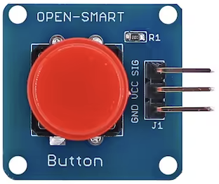
A Red Pushbutton is a momentary switch that allows current to flow when pressed and stops the flow when released. It is commonly used for user input in electronic circuits. This simple yet versatile component is essential in various applications, including:
- User Interfaces: Used in control panels, keyboards, and other input devices.
- Reset Buttons: Commonly found in electronic devices to reset the system.
- Start/Stop Controls: Utilized in machinery and equipment to start or stop operations.
- DIY Projects: Popular in hobbyist and educational projects for interactive designs.
Explore Projects Built with Red Pushbutton

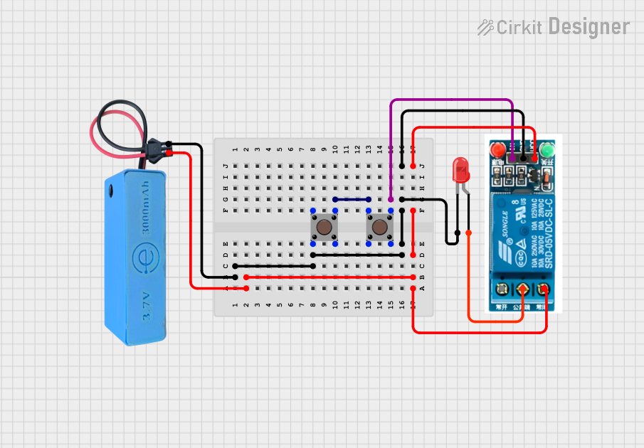
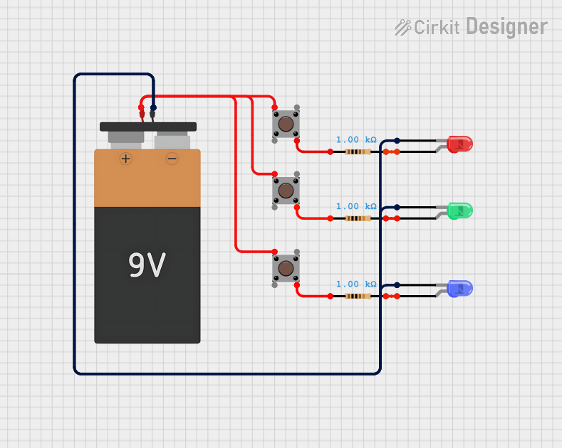
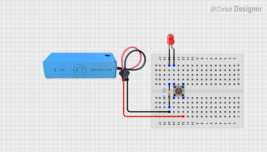
Explore Projects Built with Red Pushbutton
Technical Specifications
Key Technical Details
| Parameter | Value |
|---|---|
| Type | Momentary Switch |
| Color | Red |
| Contact Type | Normally Open (NO) |
| Voltage Rating | 12V DC |
| Current Rating | 50mA |
| Mounting Type | Through-Hole |
| Dimensions | 12mm x 12mm x 7.3mm |
Pin Configuration and Descriptions
| Pin Number | Description |
|---|---|
| 1 | Switch Terminal 1 (Normally Open) |
| 2 | Switch Terminal 2 (Common) |
Usage Instructions
How to Use the Component in a Circuit
- Identify the Pins: The Red Pushbutton has two pins. One is the normally open terminal (Pin 1), and the other is the common terminal (Pin 2).
- Connect to Power Source: Connect one pin to the positive terminal of your power source.
- Connect to Load: Connect the other pin to the input of the device you want to control (e.g., an LED or microcontroller input pin).
- Complete the Circuit: Ensure the circuit is complete by connecting the other terminal of the load to the ground.
Important Considerations and Best Practices
- Debouncing: Mechanical switches like pushbuttons can produce multiple signals when pressed. Use hardware (capacitors) or software (debouncing code) to filter out these noise signals.
- Current Limiting: Ensure the current through the pushbutton does not exceed its rating (50mA). Use a current-limiting resistor if necessary.
- Proper Mounting: Secure the pushbutton properly in your project to avoid loose connections.
Example Circuit with Arduino UNO
Here is an example of how to connect a Red Pushbutton to an Arduino UNO:
Schematic
[Arduino UNO] --- [10kΩ Resistor] --- [Pushbutton] --- [GND]
                    |
                   [Pin 2]
Code
// Define the pin for the pushbutton
const int buttonPin = 2;
// Define the pin for the LED
const int ledPin = 13;

// Variable to store the button state
int buttonState = 0;

void setup() {
  // Initialize the button pin as an input
  pinMode(buttonPin, INPUT);
  // Initialize the LED pin as an output
  pinMode(ledPin, OUTPUT);
}

void loop() {
  // Read the state of the pushbutton value
  buttonState = digitalRead(buttonPin);

  // Check if the pushbutton is pressed
  if (buttonState == HIGH) {
    // Turn LED on
    digitalWrite(ledPin, HIGH);
  } else {
    // Turn LED off
    digitalWrite(ledPin, LOW);
  }
}
Troubleshooting and FAQs
Common Issues Users Might Face
Button Not Responding:
- Solution: Check the connections and ensure the pushbutton is properly connected to the circuit. Verify that the power supply is functioning.
Multiple Signals (Bouncing):
- Solution: Implement debouncing either through hardware (capacitors) or software (debouncing code).
LED Not Lighting Up:
- Solution: Ensure the LED is connected correctly and the current-limiting resistor is in place. Verify the code logic and pin assignments.
FAQs
Q1: Can I use the Red Pushbutton with a higher voltage?
- A1: No, the Red Pushbutton is rated for a maximum of 12V DC. Using a higher voltage can damage the switch.
Q2: How do I implement software debouncing?
- A2: You can implement software debouncing by adding a small delay after detecting a button press to filter out noise. Here is an example:
void loop() {
  // Read the state of the pushbutton value
  buttonState = digitalRead(buttonPin);

  // Check if the pushbutton is pressed
  if (buttonState == HIGH) {
    // Wait for 50 milliseconds
    delay(50);
    // Check the button state again
    if (digitalRead(buttonPin) == HIGH) {
      // Turn LED on
      digitalWrite(ledPin, HIGH);
    }
  } else {
    // Turn LED off
    digitalWrite(ledPin, LOW);
  }
}
Q3: Can I use the pushbutton for AC applications?
- A3: No, the Red Pushbutton is designed for DC applications only. Using it with AC can be hazardous and may damage the component.
This documentation provides a comprehensive guide to understanding, using, and troubleshooting the Red Pushbutton in your electronic projects. Whether you are a beginner or an experienced user, this guide aims to help you make the most of this versatile component.