How to Use Step Up Boost Power Converter, Adjustable Voltage Regulator: Examples, Pinouts, and Specs
Introduction
The Youmile Step Up Boost Power Converter is a versatile and efficient DC-DC voltage regulator designed to step up a lower input voltage to a higher, adjustable output voltage. This component is widely used in applications requiring stable and adjustable power supply, such as battery-powered devices, DIY electronics projects, and portable power systems. Its compact design and high efficiency make it an excellent choice for hobbyists and professionals alike.
Explore Projects Built with Step Up Boost Power Converter, Adjustable Voltage Regulator


Explore Projects Built with Step Up Boost Power Converter, Adjustable Voltage Regulator
Common Applications and Use Cases
- Powering devices requiring higher voltage from a lower voltage source (e.g., 5V to 12V).
- DIY projects involving microcontrollers, sensors, and modules.
- Battery-powered systems, such as lithium-ion or AA battery packs.
- LED lighting systems and portable chargers.
- Solar power systems for voltage regulation.
Technical Specifications
The following table outlines the key technical details of the Youmile Step Up Boost Power Converter:
| Parameter | Specification |
|---|---|
| Input Voltage Range | 3V to 35V DC |
| Output Voltage Range | 4V to 40V DC (adjustable) |
| Maximum Output Current | 2A (continuous), 3A (peak) |
| Efficiency | Up to 92% (depending on input/output) |
| Switching Frequency | 150 kHz |
| Operating Temperature | -40°C to +85°C |
| Dimensions | 43mm x 21mm x 14mm |
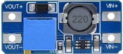
Pin Configuration and Descriptions
The module has four main pins for input and output connections:
| Pin Name | Description |
|---|---|
| VIN+ | Positive input voltage terminal (3V to 35V DC). |
| VIN- | Negative input voltage terminal (ground). |
| VOUT+ | Positive output voltage terminal (4V to 40V DC). |
| VOUT- | Negative output voltage terminal (ground). |
Usage Instructions
How to Use the Component in a Circuit
Connect the Input Voltage:
- Connect the positive terminal of your power source to the
VIN+pin. - Connect the negative terminal of your power source to the
VIN-pin. - Ensure the input voltage is within the specified range (3V to 35V DC).
- Connect the positive terminal of your power source to the
Adjust the Output Voltage:
- Use a small screwdriver to turn the onboard potentiometer (blue trimmer).
- Turn clockwise to increase the output voltage or counterclockwise to decrease it.
- Measure the output voltage across the
VOUT+andVOUT-pins using a multimeter.
Connect the Load:
- Connect the positive terminal of your load to the
VOUT+pin. - Connect the negative terminal of your load to the
VOUT-pin. - Ensure the load does not exceed the maximum output current (2A continuous, 3A peak).
- Connect the positive terminal of your load to the
Power On:
- Turn on the power source and verify the output voltage is as desired.
- Monitor the module for any signs of overheating or instability.
Important Considerations and Best Practices
- Heat Dissipation: For high current loads, consider adding a heatsink to the module to prevent overheating.
- Input Voltage: Ensure the input voltage is always lower than the desired output voltage.
- Output Voltage Adjustment: Avoid turning the potentiometer excessively to prevent damage.
- Polarity: Double-check the polarity of all connections to avoid short circuits or damage to the module.
- Load Testing: Gradually increase the load to ensure the module operates within its rated specifications.
Example: Using with an Arduino UNO
The Step Up Boost Power Converter can be used to power an Arduino UNO from a lower voltage source, such as a 5V battery pack, by stepping up the voltage to 9V.
Circuit Connection
- Connect the 5V battery pack to the
VIN+andVIN-pins of the converter. - Adjust the output voltage to 9V using the potentiometer.
- Connect the
VOUT+pin to the Arduino'sVINpin. - Connect the
VOUT-pin to the Arduino'sGNDpin.
Sample Code
Here is a simple Arduino sketch to blink an LED while powered by the Step Up Boost Power Converter:
// Blink an LED connected to pin 13 of the Arduino UNO
// Ensure the Step Up Boost Converter is providing 9V to the Arduino's VIN pin

void setup() {
  pinMode(13, OUTPUT); // Set pin 13 as an output
}

void loop() {
  digitalWrite(13, HIGH); // Turn the LED on
  delay(1000);            // Wait for 1 second
  digitalWrite(13, LOW);  // Turn the LED off
  delay(1000);            // Wait for 1 second
}
Troubleshooting and FAQs
Common Issues and Solutions
No Output Voltage:
- Verify the input voltage is within the specified range (3V to 35V DC).
- Check all connections for proper polarity and secure contact.
- Ensure the potentiometer is not turned to its minimum position.
Overheating:
- Reduce the load current to within the module's rated capacity.
- Add a heatsink or improve ventilation around the module.
Unstable Output Voltage:
- Verify the input voltage is stable and not fluctuating.
- Check for loose connections or damaged components.
Output Voltage Not Adjustable:
- Ensure the potentiometer is functioning correctly and not damaged.
- Verify the input voltage is lower than the desired output voltage.
FAQs
Q: Can this module step down voltage as well?
A: No, this is a boost converter and can only step up the input voltage to a higher output voltage.
Q: Can I use this module with a solar panel?
A: Yes, as long as the solar panel's output voltage is within the input range (3V to 35V DC).
Q: What happens if I exceed the maximum current rating?
A: Exceeding the current rating may cause the module to overheat, shut down, or become permanently damaged.
Q: Is the output voltage stable enough for sensitive electronics?
A: Yes, the module provides a stable output voltage suitable for most electronics, but additional filtering may be required for highly sensitive devices.