How to Use Reverb Transformer: Examples, Pinouts, and Specs

Introduction
A reverb transformer is an electrical component used in audio circuits to create a reverberation effect. It works by transforming the audio signal to drive a reverb tank, which produces the characteristic echo or ambient sound. Reverb transformers are commonly found in musical instruments, such as electric guitars and amplifiers, as well as in sound processing equipment for studios and live performances. They play a critical role in shaping the tonal quality and depth of the audio signal.
Explore Projects Built with Reverb Transformer
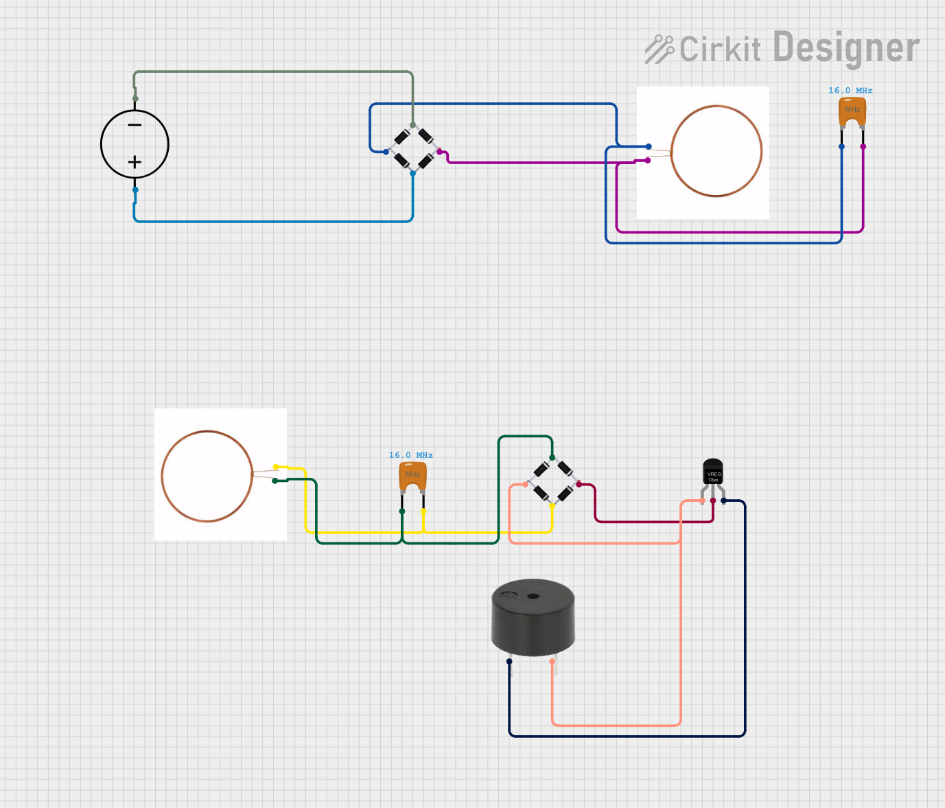

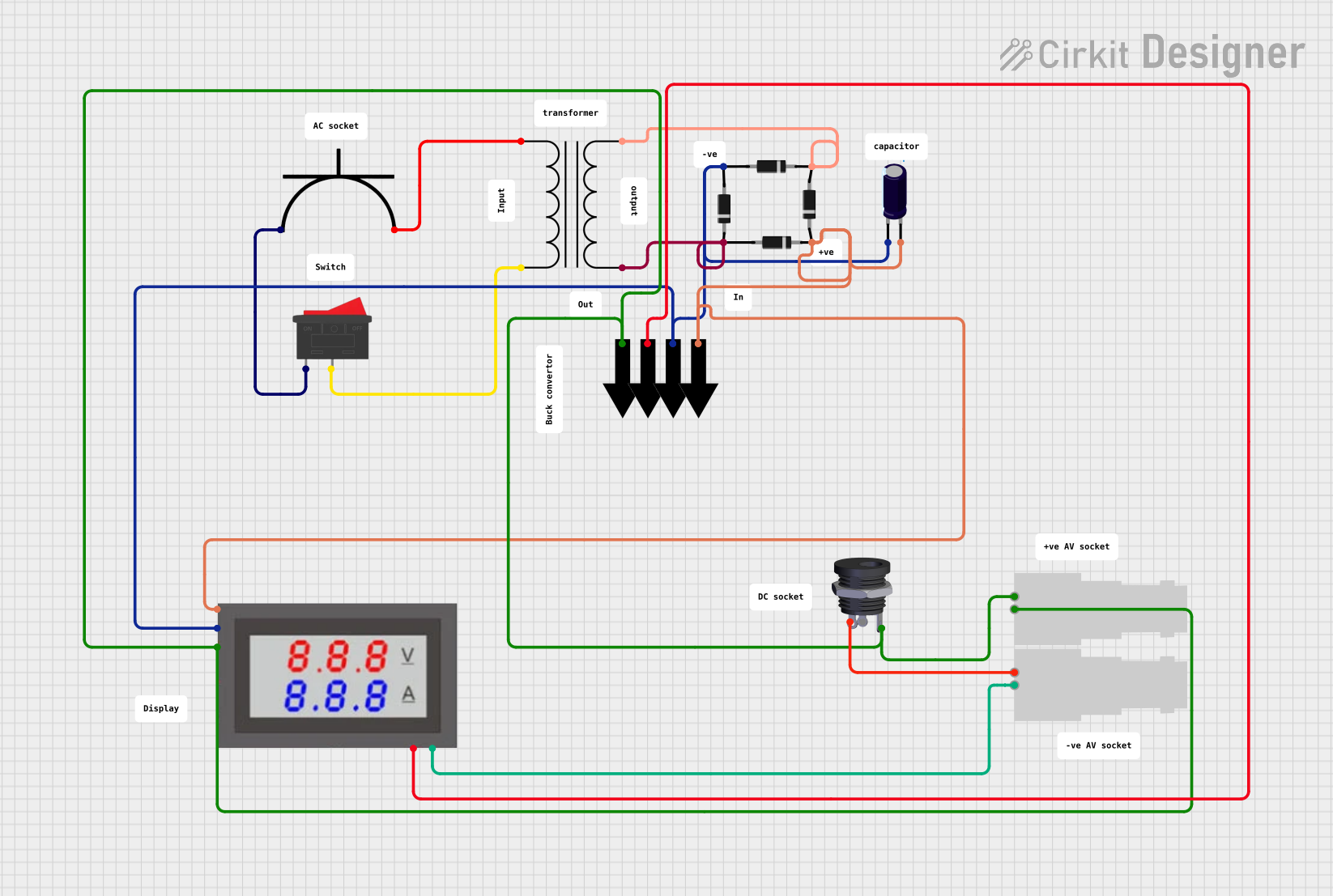
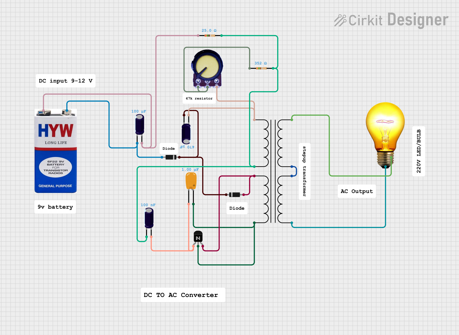
Explore Projects Built with Reverb Transformer
Common Applications and Use Cases
- Electric guitar amplifiers with built-in reverb effects
- Audio mixing consoles and sound processors
- Studio equipment for creating ambient soundscapes
- Vintage audio equipment restoration
- Custom DIY audio projects
Technical Specifications
Below are the typical technical specifications for a reverb transformer. Note that actual values may vary depending on the specific model and manufacturer.
General Specifications
- Primary Impedance: 8 Ω to 10 kΩ (depending on the circuit design)
- Secondary Impedance: 1 Ω to 4 Ω (to match the reverb tank input)
- Frequency Response: 20 Hz to 20 kHz
- Power Handling: 1 W to 5 W
- Core Material: Laminated steel or ferrite
- Mounting Style: PCB or chassis mount
Pin Configuration and Descriptions
The reverb transformer typically has four pins: two for the primary winding and two for the secondary winding. The table below describes the pin configuration:
| Pin | Name | Description |
|---|---|---|
| 1 | Primary (+) | Positive terminal of the primary winding; connects to the amplifier output. |
| 2 | Primary (-) | Negative terminal of the primary winding; connects to the amplifier ground. |
| 3 | Secondary (+) | Positive terminal of the secondary winding; connects to the reverb tank input. |
| 4 | Secondary (-) | Negative terminal of the secondary winding; connects to the reverb tank ground. |
Usage Instructions
How to Use the Reverb Transformer in a Circuit
- Connect the Primary Side:
- Attach the primary winding terminals to the output of the amplifier circuit. Ensure the polarity matches the design requirements.
- Connect the Secondary Side:
- Connect the secondary winding terminals to the input of the reverb tank. Match the impedance of the transformer to the reverb tank for optimal performance.
- Mounting:
- Secure the transformer to the PCB or chassis using screws or soldering, depending on the mounting style.
- Power On:
- Power on the circuit and test the reverb effect. Adjust the amplifier gain or reverb tank settings as needed.
Important Considerations and Best Practices
- Impedance Matching: Ensure the primary and secondary impedances of the transformer match the amplifier and reverb tank, respectively, to avoid signal loss or distortion.
- Grounding: Properly ground the transformer to minimize noise and interference in the audio signal.
- Orientation: Mount the transformer away from other magnetic components to reduce electromagnetic interference (EMI).
- Testing: Use an oscilloscope to verify the signal integrity at the transformer output.
Example: Using a Reverb Transformer with an Arduino UNO
While reverb transformers are not directly compatible with Arduino due to their analog nature, you can use an Arduino to control the reverb effect in a circuit. Below is an example of how to use an Arduino to adjust the reverb level via a digital potentiometer:
#include <Wire.h>
#include <Adafruit_MCP4725.h> // Library for the MCP4725 DAC

Adafruit_MCP4725 dac;

void setup() {
  dac.begin(0x60); // Initialize the DAC at I2C address 0x60
  Serial.begin(9600);
}

void loop() {
  int reverbLevel = analogRead(A0); // Read potentiometer value (0-1023)
  reverbLevel = map(reverbLevel, 0, 1023, 0, 4095);
  // Map the value to the DAC range (0-4095 for 12-bit resolution)

  dac.setVoltage(reverbLevel, false);
  // Set the DAC output voltage to control the reverb level

  delay(10); // Small delay for stability
}
Note: In this example, the Arduino controls a digital potentiometer or DAC, which adjusts the signal level sent to the reverb transformer.
Troubleshooting and FAQs
Common Issues and Solutions
No Reverb Effect:
- Cause: Incorrect wiring or impedance mismatch.
- Solution: Double-check the connections and ensure the transformer impedance matches the amplifier and reverb tank.
Distorted Sound:
- Cause: Overloading the transformer or improper grounding.
- Solution: Verify the input signal level and ensure proper grounding of the circuit.
Excessive Noise or Hum:
- Cause: Electromagnetic interference or poor shielding.
- Solution: Relocate the transformer away from other magnetic components and use shielded cables.
Transformer Overheating:
- Cause: Exceeding the power rating of the transformer.
- Solution: Ensure the input power does not exceed the transformer's rated power handling.
FAQs
Q1: Can I use any reverb transformer with my amplifier?
A1: No, you must select a transformer with the correct primary and secondary impedances to match your amplifier and reverb tank.
Q2: How do I test if my reverb transformer is working?
A2: Use an audio signal generator and an oscilloscope to verify the signal transformation across the primary and secondary windings.
Q3: Can I use a reverb transformer in a digital audio system?
A3: Reverb transformers are designed for analog circuits. For digital systems, consider using digital signal processing (DSP) techniques to create reverb effects.
Q4: What happens if I reverse the primary and secondary connections?
A4: Reversing the connections may result in improper signal transformation or damage to the circuit. Always follow the manufacturer's pinout diagram.