How to Use Breadboard Power Supply Breakout: Examples, Pinouts, and Specs
Introduction
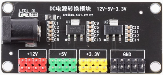
The Breadboard Power Supply Breakout is a compact and versatile module designed to provide regulated power to breadboards during prototyping and development. It is based on the AMS1117 voltage regulator and offers multiple output voltage options, typically 5V and 3.3V. This module connects directly to the power rails of a standard breadboard, making it an essential tool for hobbyists, students, and engineers working on electronic projects.
Explore Projects Built with Breadboard Power Supply Breakout


Explore Projects Built with Breadboard Power Supply Breakout
Common Applications and Use Cases
- Powering breadboard-based circuits during prototyping.
- Supplying regulated 5V or 3.3V to microcontrollers, sensors, and modules.
- Educational projects and DIY electronics.
- Testing and debugging small electronic circuits.
Technical Specifications
The Breadboard Power Supply Breakout is built around the AMS1117 voltage regulator and provides the following key specifications:
| Parameter | Value |
|---|---|
| Input Voltage Range | 6.5V to 12V DC |
| Output Voltage Options | 5V and 3.3V |
| Maximum Output Current | 800mA (depending on input voltage) |
| Power Input Options | DC barrel jack or USB connector |
| Output Interface | Standard breadboard power rails |
| Dimensions | 5.3cm x 3.5cm x 1.5cm |
Pin Configuration and Descriptions
The module has several key pins and connectors for input and output:
| Pin/Connector | Description |
|---|---|
| DC Barrel Jack | Accepts 6.5V to 12V DC input for powering the module. |
| USB Connector | Alternative input option for powering the module via a USB cable. |
| 5V Output Pin | Provides regulated 5V output to the breadboard power rail. |
| 3.3V Output Pin | Provides regulated 3.3V output to the breadboard power rail. |
| Power Switch | Toggles the power supply on or off. |
| Jumper Selectors | Allows selection between 5V and 3.3V output for each power rail. |
| GND Pins | Ground connections for the breadboard power rails. |
Usage Instructions
How to Use the Component in a Circuit
Connect the Power Supply:
- Plug the Breadboard Power Supply Breakout into the power rails of your breadboard.
- Use either the DC barrel jack (6.5V to 12V) or the USB connector to supply power to the module.
Set the Output Voltage:
- Use the onboard jumpers to select the desired output voltage (5V or 3.3V) for each power rail.
Power On the Module:
- Toggle the power switch to the "ON" position. The onboard LED will light up, indicating that the module is active.
Connect Your Circuit:
- Use the breadboard power rails to distribute power to your components and modules.
Important Considerations and Best Practices
- Input Voltage: Ensure the input voltage is within the specified range (6.5V to 12V). Exceeding this range may damage the module.
- Current Limitations: The maximum output current is 800mA. Avoid overloading the module to prevent overheating or damage.
- Heat Dissipation: The AMS1117 regulator may become warm during operation. Ensure adequate ventilation to prevent overheating.
- Polarity: Double-check the polarity of your input power source to avoid damaging the module.
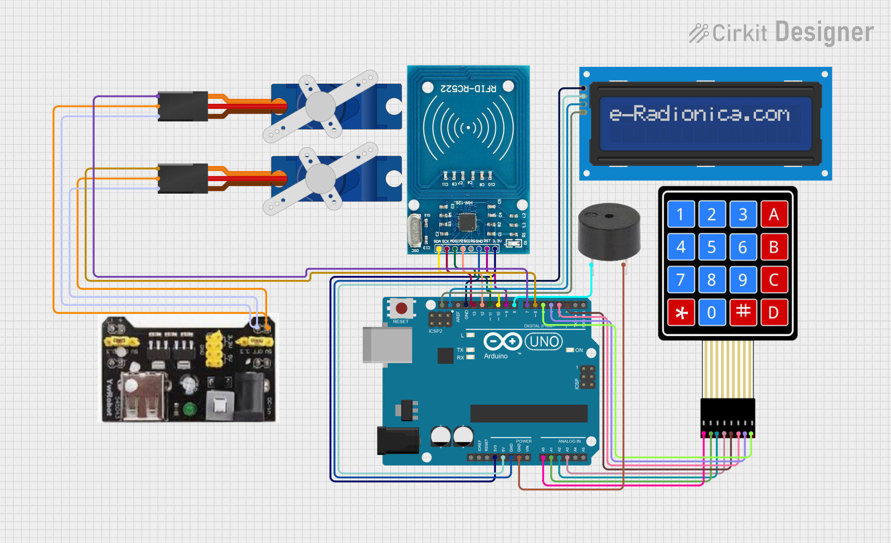
Example: Using with an Arduino UNO
The Breadboard Power Supply Breakout can be used to power an Arduino UNO via the breadboard. Below is an example of how to blink an LED using the module:
Circuit Setup
- Connect the Breadboard Power Supply Breakout to the breadboard.
- Set the output voltage to 5V using the jumper.
- Power the module using a 9V DC adapter.
- Connect the Arduino UNO's VIN pin to the breadboard's 5V rail and GND to the GND rail.
- Connect an LED and a 220-ohm resistor to pin 13 of the Arduino.
Arduino Code
// Blink an LED connected to pin 13 of the Arduino UNO
void setup() {
  pinMode(13, OUTPUT); // Set pin 13 as an output
}

void loop() {
  digitalWrite(13, HIGH); // Turn the LED on
  delay(1000);            // Wait for 1 second
  digitalWrite(13, LOW);  // Turn the LED off
  delay(1000);            // Wait for 1 second
}
Troubleshooting and FAQs
Common Issues and Solutions
Module Not Powering On:
- Ensure the input voltage is within the specified range (6.5V to 12V).
- Check the power switch and ensure it is in the "ON" position.
- Verify the polarity of the input power source.
No Output Voltage:
- Confirm that the jumpers are correctly set to the desired output voltage (5V or 3.3V).
- Check for loose connections between the module and the breadboard.
Overheating:
- Ensure the module is not overloaded. The maximum output current is 800mA.
- Provide adequate ventilation to dissipate heat from the AMS1117 regulator.
LED Not Lighting Up:
- Verify the LED polarity (longer leg is the anode, shorter leg is the cathode).
- Check the resistor value (220 ohms is recommended for 5V circuits).
FAQs
Q: Can I use this module to power a Raspberry Pi?
A: No, the module cannot supply sufficient current for a Raspberry Pi. It is better suited for low-power devices like microcontrollers and sensors.
Q: Can I use both 5V and 3.3V outputs simultaneously?
A: Yes, you can configure one power rail for 5V and the other for 3.3V using the jumpers.
Q: What happens if I exceed the input voltage range?
A: Exceeding the input voltage range may damage the AMS1117 regulator and render the module unusable. Always use a regulated power source within the specified range.
Q: Is the module compatible with all breadboards?
A: The module is designed for standard breadboards with 2 power rails on each side. Ensure your breadboard matches this configuration.