How to Use pin board: Examples, Pinouts, and Specs
Introduction
A pin board, also known as a breadboard, is a reusable platform used for prototyping electronic circuits. It allows components to be easily inserted and connected without soldering, facilitating quick adjustments and testing. Pin boards are widely used in educational settings, hobbyist projects, and professional prototyping due to their versatility and ease of use.
Explore Projects Built with pin board

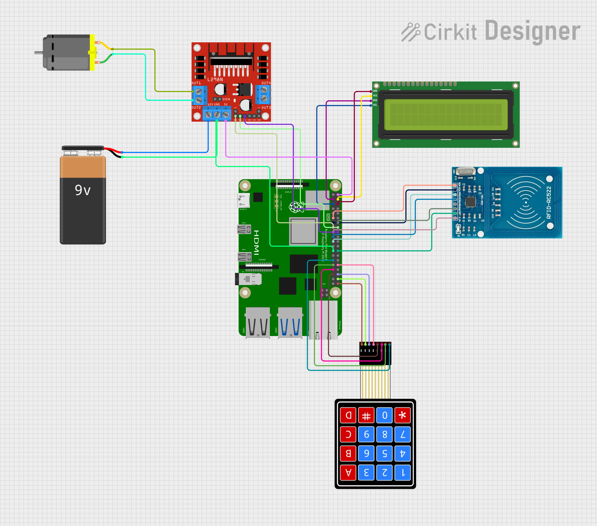
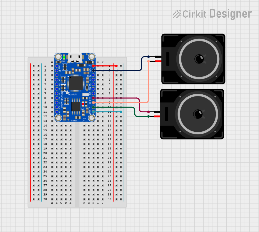

Explore Projects Built with pin board
Common Applications and Use Cases
- Rapid prototyping of electronic circuits
- Testing and debugging circuit designs
- Educational demonstrations and learning tools for electronics
- Temporary circuit assembly for experimentation
- Connecting microcontrollers (e.g., Arduino, Raspberry Pi) to external components
Technical Specifications
Pin boards come in various sizes and configurations, but the following are typical specifications for a standard breadboard:
| Specification | Details |
|---|---|
| Material | ABS plastic housing with nickel-plated phosphor bronze contacts |
| Power Rails | Two sets of power rails (positive and negative) on each side |
| Terminal Strips | 630 tie points (typical for a standard breadboard) |
| Voltage Rating | Up to 12V DC |
| Current Rating | Up to 1A per contact |
| Dimensions | 165mm x 55mm x 10mm (standard size) |
| Pin Spacing | 2.54mm (0.1 inch) |
| Compatibility | Compatible with standard 22-28 AWG wires and most through-hole components |
Pin Configuration and Descriptions
The breadboard is divided into sections for easy circuit assembly. Below is a description of its layout:
| Section | Description |
|---|---|
| Power Rails | Horizontal rows on the top and bottom edges for distributing power and ground. |
| Terminal Strips | Vertical columns in the center for connecting components. Each column is split |
| into two halves by a central gap, isolating the left and right sides. | |
| Central Gap | A gap in the middle of the breadboard to accommodate dual-inline package (DIP) |
| integrated circuits (ICs). |
Usage Instructions
How to Use the Pin Board in a Circuit
Power Supply Setup:
- Connect the positive terminal of your power source to the red power rail.
- Connect the negative terminal (ground) to the blue power rail.
- Use jumper wires to distribute power to different sections of the board.
Component Placement:
- Insert components (e.g., resistors, capacitors, LEDs) into the terminal strip holes.
- Ensure that the leads of each component are properly aligned with the desired connections.
Connecting Wires:
- Use 22-28 AWG solid-core wires for connections.
- Insert one end of the wire into the terminal strip and the other end into the desired connection point.
Testing the Circuit:
- Double-check all connections for accuracy.
- Power on the circuit and observe its behavior. Make adjustments as needed.
Important Considerations and Best Practices
- Avoid exceeding the voltage and current ratings of the breadboard to prevent damage.
- Use color-coded wires (e.g., red for positive, black for ground) for better organization.
- Keep wires short and tidy to minimize confusion and reduce the risk of accidental disconnections.
- Always disconnect the power supply before making changes to the circuit.
Example: Connecting an LED to an Arduino UNO
Below is an example of how to use a pin board to connect an LED to an Arduino UNO:
Circuit Setup
- Place the LED on the breadboard, ensuring the longer leg (anode) is connected to a resistor.
- Connect the other end of the resistor to a digital pin on the Arduino (e.g., pin 9).
- Connect the shorter leg (cathode) of the LED to the ground rail.
- Use a jumper wire to connect the ground rail to the Arduino's GND pin.
Arduino Code
// This code blinks an LED connected to pin 9 of the Arduino UNO.

const int ledPin = 9; // Define the pin connected to the LED

void setup() {
  pinMode(ledPin, OUTPUT); // Set the LED pin as an output
}

void loop() {
  digitalWrite(ledPin, HIGH); // Turn the LED on
  delay(1000);                // Wait for 1 second
  digitalWrite(ledPin, LOW);  // Turn the LED off
  delay(1000);                // Wait for 1 second
}
Troubleshooting and FAQs
Common Issues and Solutions
Problem: Components are not functioning as expected.
- Solution: Check all connections for accuracy and ensure components are properly seated in the breadboard.
Problem: The circuit is not receiving power.
- Solution: Verify that the power supply is connected to the correct rails and is turned on.
Problem: Intermittent connections or loose components.
- Solution: Ensure that all wires and components are firmly inserted into the breadboard holes.
Problem: Overheating components or burning smell.
- Solution: Disconnect power immediately and check for short circuits or components exceeding their ratings.
FAQs
Q: Can I use a breadboard for high-power circuits?
A: No, breadboards are designed for low-power circuits (up to 12V and 1A). For high-power applications, use soldered connections and appropriate components.Q: How do I clean a breadboard?
A: Use compressed air to remove dust and debris. Avoid using liquids, as they can damage the contacts.Q: Can I reuse a breadboard indefinitely?
A: Breadboards are reusable, but the contacts may wear out over time with frequent use. Replace the breadboard if connections become unreliable.Q: Are breadboards compatible with surface-mount components?
A: Breadboards are designed for through-hole components. Use adapter boards to connect surface-mount components.