How to Use MAX30102: Examples, Pinouts, and Specs
Introduction
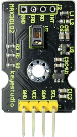
The MAX30102, manufactured by Keyestudio, is a pulse oximeter and heart-rate sensor designed for non-invasive health monitoring. It utilizes photoplethysmography (PPG) technology to measure blood oxygen saturation (SpO2) and heart rate. The sensor integrates red and infrared LEDs, a photodetector, optical elements, and low-noise electronics in a compact package, making it ideal for wearable devices and portable health monitoring systems.
Explore Projects Built with MAX30102


Explore Projects Built with MAX30102
Common Applications and Use Cases
- Wearable fitness trackers and smartwatches
- Medical devices for SpO2 and heart rate monitoring
- Health monitoring systems for athletes
- Research and development in biomedical engineering
- DIY health monitoring projects
Technical Specifications
The MAX30102 is a highly integrated sensor with the following key specifications:
| Parameter | Value |
|---|---|
| Operating Voltage | 1.8V (core) and 3.3V (I/O) |
| Supply Voltage Range | 1.7V to 2.0V (core), 3.0V to 3.6V (I/O) |
| Operating Current | 600 µA (typical) |
| Standby Current | 0.7 µA (typical) |
| LED Wavelengths | Red: 660 nm, Infrared: 880 nm |
| Communication Interface | I2C (7-bit address: 0x57) |
| Sampling Rate | Programmable (up to 1000 Hz) |
| Operating Temperature Range | -40°C to +85°C |
| Dimensions | 5.6 mm x 3.3 mm x 1.55 mm |
Pin Configuration and Descriptions
The MAX30102 module typically comes with the following pinout:
| Pin Name | Description |
|---|---|
| VIN | Power supply input (3.3V or 5V, depending on module) |
| GND | Ground |
| SDA | I2C data line |
| SCL | I2C clock line |
| INT | Interrupt output (active low) |
Usage Instructions
How to Use the MAX30102 in a Circuit
- Power Supply: Connect the VIN pin to a 3.3V or 5V power source (depending on the module) and GND to ground.
- I2C Communication: Connect the SDA and SCL pins to the corresponding I2C pins on your microcontroller (e.g., Arduino UNO: A4 for SDA, A5 for SCL).
- Interrupt Pin: Optionally, connect the INT pin to a digital input pin on your microcontroller to handle interrupts.
- Pull-Up Resistors: Ensure that the I2C lines (SDA and SCL) have pull-up resistors (typically 4.7 kΩ) if not already included on the module.
Important Considerations and Best Practices
- Ambient Light: Minimize ambient light interference by enclosing the sensor in a dark environment or using it in low-light conditions.
- Skin Contact: For accurate readings, ensure the sensor is in direct contact with the skin.
- Sampling Rate: Adjust the sampling rate based on your application to balance power consumption and data accuracy.
- I2C Address: The default I2C address of the MAX30102 is 0x57. Ensure no other devices on the I2C bus share this address.
Example Code for Arduino UNO
Below is an example of how to interface the MAX30102 with an Arduino UNO using the Adafruit MAX30102 library:
#include <Wire.h>
#include "Adafruit_MAX30102.h"

// Create an instance of the MAX30102 sensor
Adafruit_MAX30102 max30102;

void setup() {
  Serial.begin(9600); // Initialize serial communication
  while (!Serial);    // Wait for the serial monitor to open

  // Initialize the MAX30102 sensor
  if (!max30102.begin()) {
    Serial.println("MAX30102 not detected. Check connections!");
    while (1); // Halt execution if the sensor is not found
  }
  Serial.println("MAX30102 initialized successfully!");
}

void loop() {
  // Variables to store sensor readings
  int redValue, irValue;

  // Read red and infrared LED values
  if (max30102.check() == true) {
    redValue = max30102.getRed();
    irValue = max30102.getIR();

    // Print the readings to the serial monitor
    Serial.print("Red: ");
    Serial.print(redValue);
    Serial.print(" | IR: ");
    Serial.println(irValue);
  } else {
    Serial.println("No data available from MAX30102.");
  }

  delay(100); // Delay to control the sampling rate
}
Notes:
- Install the Adafruit MAX30102 library via the Arduino Library Manager before running the code.
- Ensure proper wiring and verify the I2C address if the sensor is not detected.
Troubleshooting and FAQs
Common Issues and Solutions
Sensor Not Detected:
- Cause: Incorrect wiring or I2C address mismatch.
- Solution: Verify the connections and ensure the I2C address is set to 0x57 in the code.
Inaccurate Readings:
- Cause: Poor skin contact or excessive ambient light.
- Solution: Ensure the sensor is in direct contact with the skin and minimize ambient light interference.
No Data Available:
- Cause: Sampling rate too low or sensor not initialized properly.
- Solution: Check the initialization code and increase the sampling rate if necessary.
Interrupt Pin Not Functioning:
- Cause: Interrupt pin not connected or configured in the code.
- Solution: Connect the INT pin to a digital input pin and configure it in the code.
FAQs
Q: Can the MAX30102 be powered with 5V?
A: Yes, if the module includes a voltage regulator. Otherwise, the sensor itself operates at 1.8V (core) and 3.3V (I/O).
Q: What is the maximum distance between the sensor and the microcontroller?
A: The I2C bus typically supports distances up to 1 meter. For longer distances, consider using I2C extenders.
Q: Can the MAX30102 measure SpO2 and heart rate simultaneously?
A: Yes, the sensor can measure both parameters simultaneously by analyzing the red and infrared LED signals.
Q: Is the MAX30102 suitable for medical-grade applications?
A: The MAX30102 is designed for general-purpose health monitoring and is not certified for medical-grade applications.