
How to Use LSM303 Breakout Board - Tilt-Compensated Compass: Examples, Pinouts, and Specs
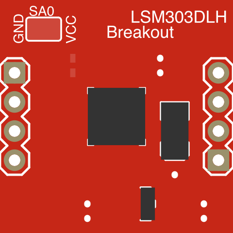
 Design with LSM303 Breakout Board - Tilt-Compensated Compass in Cirkit Designer
Introduction
The LSM303 Breakout Board by SparkFun Electronics is a compact sensor module that integrates a 3-axis accelerometer and a 3-axis magnetometer. This combination enables precise tilt-compensated heading and orientation detection, making it an excellent choice for navigation, motion tracking, and robotics applications. The module is designed for ease of use, with I2C communication and a small form factor suitable for embedded systems.
Explore Projects Built with LSM303 Breakout Board - Tilt-Compensated Compass
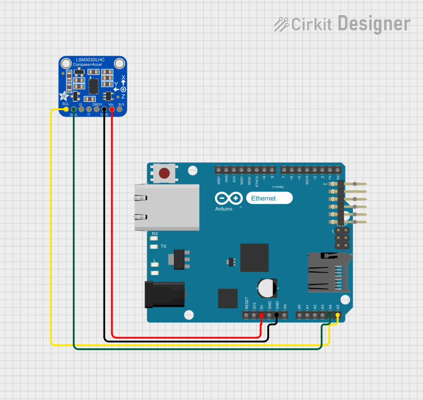 Open Project in Cirkit Designer
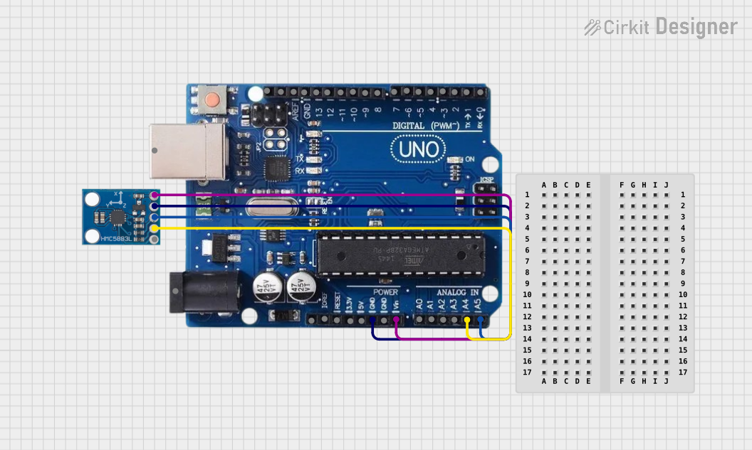 Open Project in Cirkit Designer
 Open Project in Cirkit Designer
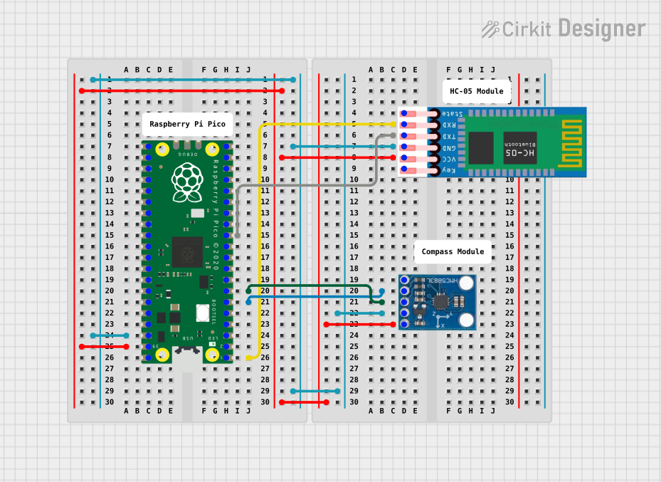 Open Project in Cirkit Designer
Explore Projects Built with LSM303 Breakout Board - Tilt-Compensated Compass
Open Project in Cirkit DesignerOpen Project in Cirkit DesignerOpen Project in Cirkit DesignerOpen Project in Cirkit DesignerCommon Applications
- Electronic compasses
- Autonomous navigation systems (e.g., drones, robots)
- Motion tracking and gesture recognition
- Augmented reality devices
- Wearable technology
Technical Specifications
The LSM303 Breakout Board is based on the STMicroelectronics LSM303DLHC sensor. Below are the key technical details:
General Specifications
| Parameter | Value |
|---|---|
| Accelerometer Range | ±2g, ±4g, ±8g, ±16g |
| Magnetometer Range | ±1.3 to ±8.1 gauss |
| Communication Interface | I2C |
| Operating Voltage | 3.3V to 5V |
| Current Consumption | ~110 µA (accelerometer), ~100 µA (magnetometer) |
| Operating Temperature | -40°C to +85°C |
| Dimensions | 0.8" x 0.8" (20.3mm x 20.3mm) |
Pin Configuration
The breakout board has the following pin layout:
| Pin Name | Description |
|---|---|
| VIN | Power input (3.3V to 5V) |
| GND | Ground |
| SDA | I2C data line |
| SCL | I2C clock line |
| DRDY | Data ready interrupt (optional) |
| INT1 | Interrupt 1 (configurable for accelerometer) |
| INT2 | Interrupt 2 (configurable for magnetometer) |
Usage Instructions
Connecting the LSM303 to an Arduino UNO
To use the LSM303 Breakout Board with an Arduino UNO, follow these steps:
Wiring:
- Connect the
VINpin to the Arduino's5Vpin. - Connect the
GNDpin to the Arduino'sGNDpin. - Connect the
SDApin to the Arduino'sA4pin (I2C data line). - Connect the
SCLpin to the Arduino'sA5pin (I2C clock line).
- Connect the
Install Required Libraries:
- Install the SparkFun LSM303 library via the Arduino Library Manager. Go to Sketch > Include Library > Manage Libraries, search for "SparkFun LSM303," and install it.
Example Code: Use the following example code to read accelerometer and magnetometer data:
#include <Wire.h>
#include <SparkFunLSM303C.h>

// Create an LSM303 object
LSM303C myLSM303;

void setup() {
  Serial.begin(9600); // Initialize serial communication
  Wire.begin();       // Initialize I2C communication

  // Initialize the LSM303 sensor
  if (myLSM303.begin() == false) {
    Serial.println("LSM303 not detected. Check connections.");
    while (1); // Halt execution if sensor is not detected
  }

  Serial.println("LSM303 initialized successfully!");
}

void loop() {
  // Read accelerometer data
  float accelX = myLSM303.readAccelX();
  float accelY = myLSM303.readAccelY();
  float accelZ = myLSM303.readAccelZ();

  // Read magnetometer data
  float magX = myLSM303.readMagX();
  float magY = myLSM303.readMagY();
  float magZ = myLSM303.readMagZ();

  // Print accelerometer data
  Serial.print("Accel (X, Y, Z): ");
  Serial.print(accelX, 2); Serial.print(", ");
  Serial.print(accelY, 2); Serial.print(", ");
  Serial.println(accelZ, 2);

  // Print magnetometer data
  Serial.print("Mag (X, Y, Z): ");
  Serial.print(magX, 2); Serial.print(", ");
  Serial.print(magY, 2); Serial.print(", ");
  Serial.println(magZ, 2);

  delay(500); // Wait 500ms before the next reading
}
Important Considerations
- Power Supply: Ensure the module is powered within the specified voltage range (3.3V to 5V). Exceeding this range may damage the sensor.
- I2C Pull-Up Resistors: The breakout board includes pull-up resistors on the I2C lines. If your system already has pull-ups, you may need to disable them to avoid conflicts.
- Calibration: For accurate readings, calibrate the accelerometer and magnetometer to account for environmental factors and sensor offsets.
- Orientation: Mount the sensor securely and ensure it is aligned with your system's coordinate axes for consistent results.
Troubleshooting and FAQs
Common Issues
Sensor Not Detected:
- Cause: Incorrect wiring or I2C address mismatch.
- Solution: Double-check the connections and ensure the I2C address matches the library's default (0x1E for the magnetometer, 0x19 for the accelerometer).
Inaccurate Readings:
- Cause: Lack of calibration or magnetic interference.
- Solution: Perform a calibration routine and ensure the sensor is away from ferromagnetic materials or strong magnetic fields.
No Data Output:
- Cause: Incorrect library installation or initialization failure.
- Solution: Verify that the SparkFun LSM303 library is installed and that the
begin()function returnstrue.
FAQs
Q1: Can I use the LSM303 with a 3.3V microcontroller?
A1: Yes, the breakout board is compatible with both 3.3V and 5V systems.
Q2: How do I calibrate the magnetometer?
A2: Rotate the sensor in all directions to collect data for a full 3D calibration. Use software tools or algorithms to compute offsets and scaling factors.
Q3: What is the maximum I2C clock speed supported?
A3: The LSM303 supports I2C clock speeds up to 400kHz (Fast Mode).
Q4: Can I use the LSM303 for tilt sensing only?
A4: Yes, you can use the accelerometer independently for tilt and motion detection without using the magnetometer.