How to Use Cardputer: Examples, Pinouts, and Specs

Introduction
The Cardputer by M5Stack is a compact computing device that integrates a microcontroller and various peripherals into a single, card-sized form factor. Designed for embedded systems and IoT applications, the Cardputer offers a versatile platform for developers to create innovative solutions. Its small size, combined with powerful features, makes it ideal for portable devices, smart home systems, industrial automation, and rapid prototyping.
Explore Projects Built with Cardputer
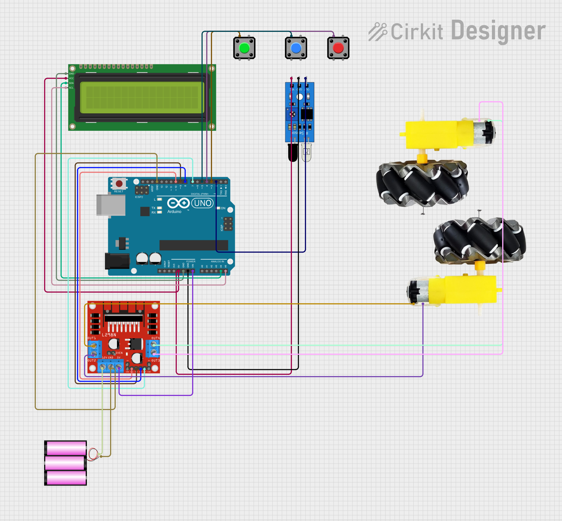
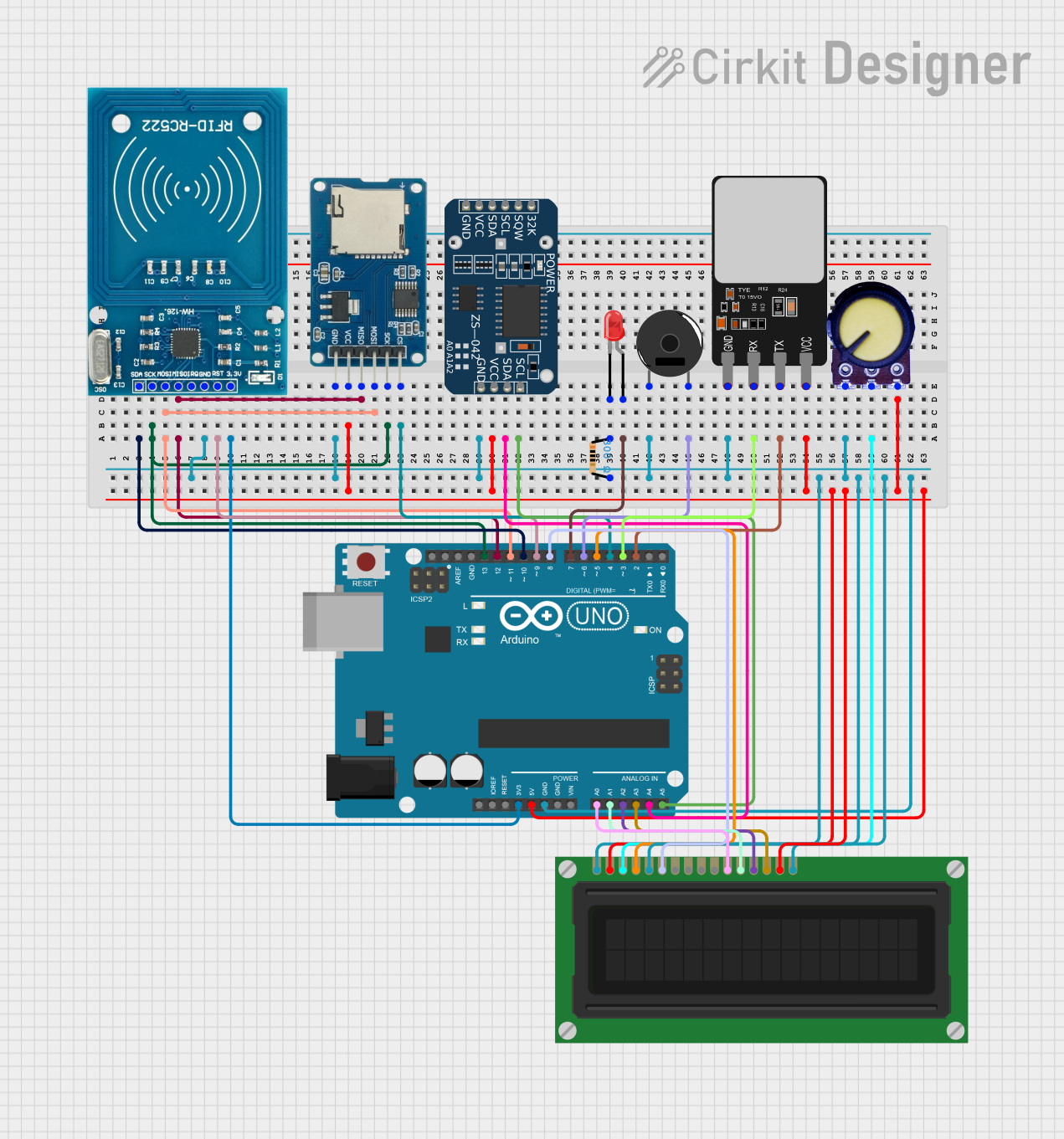
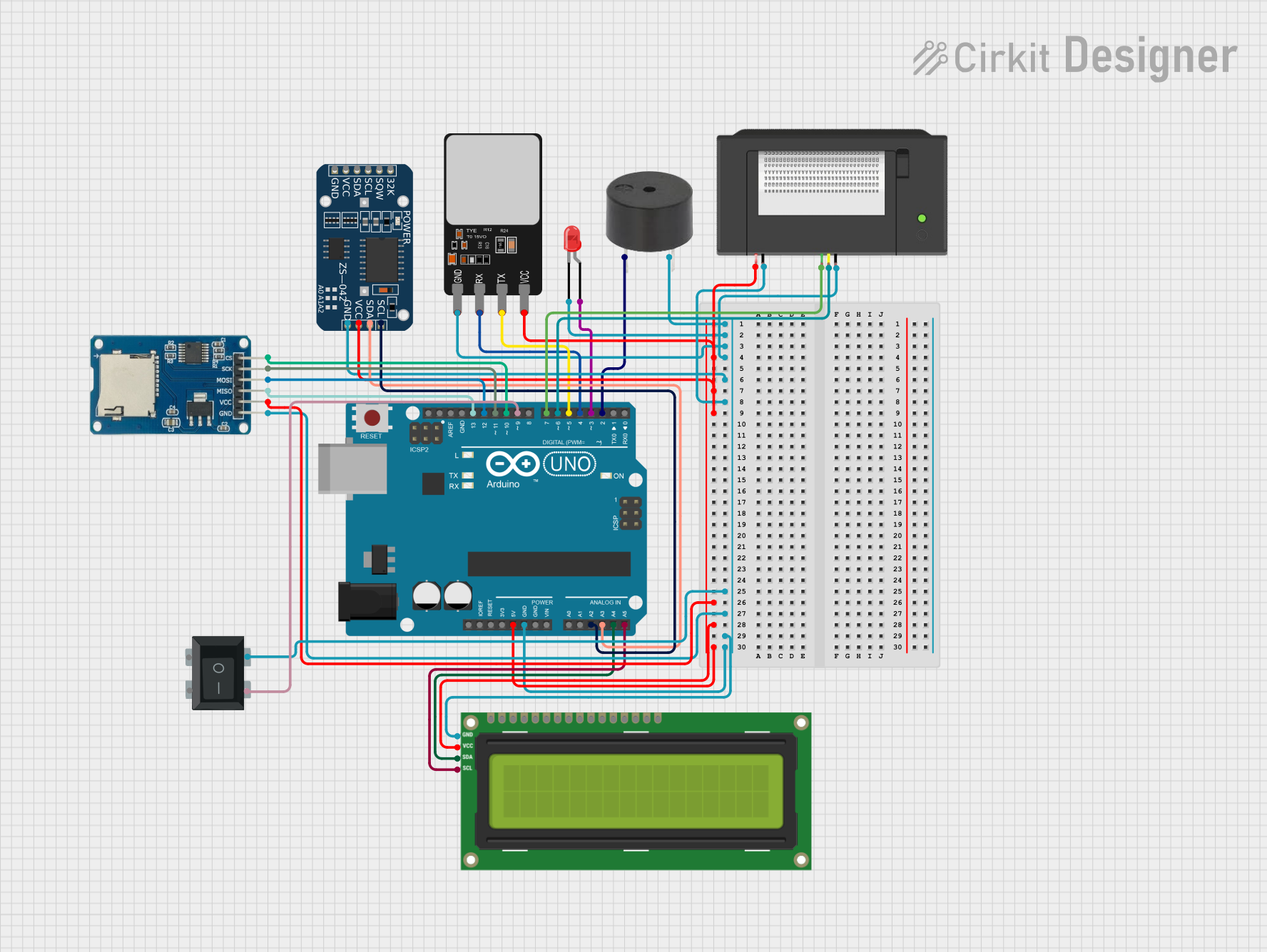

Explore Projects Built with Cardputer
Common Applications and Use Cases
- IoT (Internet of Things) devices and systems
- Portable data logging and monitoring
- Smart home automation
- Industrial control and automation
- Educational projects and prototyping
- Wearable technology
Technical Specifications
The Cardputer is equipped with a range of features to support diverse applications. Below are its key technical specifications:
General Specifications
| Feature | Specification |
|---|---|
| Microcontroller | ESP32 (dual-core, 240 MHz) |
| Flash Memory | 16 MB |
| RAM | 8 MB |
| Display | 1.14-inch TFT LCD (135x240 resolution) |
| Connectivity | Wi-Fi 802.11 b/g/n, Bluetooth 4.2 |
| Power Supply | 3.7V LiPo battery or USB-C (5V) |
| Dimensions | 85mm x 54mm x 6mm |
Pin Configuration and Descriptions
The Cardputer features a GPIO header for external connections. Below is the pinout and description:
| Pin Number | Pin Name | Function |
|---|---|---|
| 1 | GND | Ground |
| 2 | 3V3 | 3.3V Power Output |
| 3 | GPIO21 | I2C SDA / General Purpose I/O |
| 4 | GPIO22 | I2C SCL / General Purpose I/O |
| 5 | GPIO23 | SPI MOSI / General Purpose I/O |
| 6 | GPIO19 | SPI MISO / General Purpose I/O |
| 7 | GPIO18 | SPI SCK / General Purpose I/O |
| 8 | GPIO5 | PWM / General Purpose I/O |
| 9 | GPIO16 | UART RX / General Purpose I/O |
| 10 | GPIO17 | UART TX / General Purpose I/O |
Usage Instructions
How to Use the Cardputer in a Circuit
- Powering the Cardputer:
- Connect a 3.7V LiPo battery to the designated connector, or power the device via the USB-C port using a 5V power source.
- Connecting Peripherals:
- Use the GPIO header to connect sensors, actuators, or other peripherals. Ensure that the voltage and current requirements of the connected devices are compatible with the Cardputer's specifications.
- Programming the Cardputer:
- The Cardputer can be programmed using the Arduino IDE or MicroPython. Install the necessary drivers and libraries for the ESP32 microcontroller.
Important Considerations and Best Practices
- Voltage Levels: Ensure that all connected peripherals operate at 3.3V logic levels to avoid damaging the GPIO pins.
- Heat Management: While the Cardputer is efficient, prolonged operation at high loads may generate heat. Ensure proper ventilation if used in enclosed spaces.
- Firmware Updates: Regularly update the firmware to access the latest features and bug fixes.
Example: Connecting to an Arduino UNO
The Cardputer can communicate with an Arduino UNO via UART. Below is an example Arduino sketch to send data to the Cardputer:
// Example Arduino code to send data to the Cardputer via UART
void setup() {
  Serial.begin(115200); // Initialize serial communication at 115200 baud
  delay(1000);          // Wait for the Cardputer to initialize
}

void loop() {
  Serial.println("Hello, Cardputer!"); // Send a message to the Cardputer
  delay(1000);                         // Wait 1 second before sending again
}
Troubleshooting and FAQs
Common Issues and Solutions
Cardputer Not Powering On:
- Ensure the battery is charged or the USB-C cable is properly connected to a power source.
- Check for loose connections or damaged cables.
Unable to Upload Code:
- Verify that the correct COM port is selected in the Arduino IDE or other programming environment.
- Ensure the ESP32 board package is installed in the Arduino IDE.
Wi-Fi or Bluetooth Not Working:
- Check that the correct credentials or pairing settings are used.
- Ensure the firmware is up to date.
Peripherals Not Responding:
- Confirm that the GPIO pins are correctly configured in the code.
- Check the wiring and ensure the peripherals are powered.
FAQs
Q: Can the Cardputer be powered directly from a 5V source?
A: Yes, the Cardputer can be powered via the USB-C port using a 5V source.
Q: Is the Cardputer compatible with MicroPython?
A: Yes, the Cardputer supports MicroPython, making it a versatile choice for developers.
Q: What is the maximum current output of the 3.3V pin?
A: The 3.3V pin can supply up to 500mA, depending on the power source.
Q: Can I use the Cardputer for battery-powered applications?
A: Yes, the Cardputer is designed for battery-powered applications and includes a LiPo battery connector.
By following this documentation, you can effectively integrate the Cardputer into your projects and troubleshoot common issues with ease.