How to Use Arduino MEGA 2560 With WiFi Built-in - ESP8266: Examples, Pinouts, and Specs
Introduction
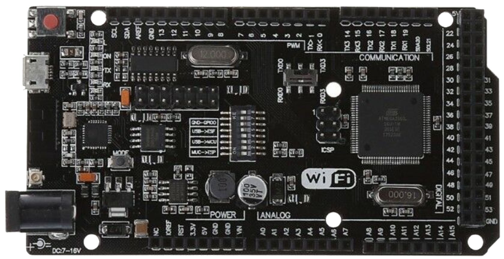
The Arduino MEGA 2560 With WiFi Built-in - ESP8266 is a versatile microcontroller board that combines the power of the ATmega2560 microcontroller with the connectivity of the ESP8266 WiFi module. This integration allows users to create advanced IoT (Internet of Things) projects with ease, enabling seamless communication between devices and the internet.
This board is ideal for applications requiring a large number of I/O pins, high processing power, and wireless connectivity. It is particularly suited for:
- Home automation systems
- Remote monitoring and control
- IoT-based data logging
- Robotics and industrial automation
- Wireless sensor networks
Explore Projects Built with Arduino MEGA 2560 With WiFi Built-in - ESP8266
Explore Projects Built with Arduino MEGA 2560 With WiFi Built-in - ESP8266
Technical Specifications
Key Technical Details
| Feature | Specification |
|---|---|
| Microcontroller | ATmega2560 |
| Operating Voltage | 5V |
| Input Voltage (recommended) | 7-12V |
| Input Voltage (limit) | 6-20V |
| Digital I/O Pins | 54 (15 of which provide PWM output) |
| Analog Input Pins | 16 |
| Flash Memory | 256 KB (8 KB used by bootloader) |
| SRAM | 8 KB |
| EEPROM | 4 KB |
| Clock Speed | 16 MHz |
| WiFi Module | ESP8266 (supports 802.11 b/g/n, AP/STA modes) |
| Communication Interfaces | UART, SPI, I2C, WiFi |
| USB Interface | USB Type-B |
| Dimensions | 101.52 mm x 53.3 mm |
Pin Configuration and Descriptions
ATmega2560 Pinout
| Pin Number | Pin Name | Description |
|---|---|---|
| 1-54 | Digital I/O | General-purpose digital input/output pins. Pins 2-13 support PWM output. |
| A0-A15 | Analog Input | Analog input pins for reading sensor data (10-bit resolution). |
| 0 (RX0) | Serial RX | UART Receive pin for Serial0 communication. |
| 1 (TX0) | Serial TX | UART Transmit pin for Serial0 communication. |
| 20 (SDA) | I2C Data | I2C data line for communication with I2C devices. |
| 21 (SCL) | I2C Clock | I2C clock line for communication with I2C devices. |
| 50-53 | SPI Pins | SPI communication pins (MISO, MOSI, SCK, SS). |
| RESET | Reset | Resets the microcontroller. |
| 3.3V | Power Output | Provides 3.3V output for external components. |
| 5V | Power Output | Provides 5V output for external components. |
| GND | Ground | Ground connection. |
ESP8266 WiFi Module Pinout
| Pin Name | Description |
|---|---|
| TX | Transmit pin for serial communication with the ATmega2560. |
| RX | Receive pin for serial communication with the ATmega2560. |
| EN/CH_PD | Enable pin to activate the ESP8266 module. |
| GPIO0 | General-purpose I/O pin, often used for boot mode selection. |
| GPIO2 | General-purpose I/O pin. |
| RST | Reset pin for the ESP8266 module. |
| VCC | Power input (3.3V). |
| GND | Ground connection. |
Usage Instructions
How to Use the Component in a Circuit
Powering the Board:
- Connect the board to a power source using a USB cable or an external power supply (7-12V recommended).
- Ensure the power supply is stable to avoid damage to the board or connected components.
Programming the ATmega2560:
- Use the Arduino IDE to upload sketches to the ATmega2560 microcontroller via the USB connection.
- Select the correct board (
Arduino Mega 2560) and port in the Arduino IDE.
Configuring the ESP8266 WiFi Module:
- The ESP8266 can be programmed separately or controlled via AT commands from the ATmega2560.
- To use AT commands, establish a serial connection between the ATmega2560 and the ESP8266.
Connecting to WiFi:
- Use the ESP8266 to connect to a WiFi network in either Station (STA) or Access Point (AP) mode.
- Example code for connecting to a WiFi network is provided below.
Interfacing with Sensors and Actuators:
- Connect sensors to the analog or digital pins of the ATmega2560.
- Use the digital I/O pins to control actuators like relays, motors, or LEDs.
Important Considerations and Best Practices
- Voltage Levels: The ESP8266 operates at 3.3V. Use a level shifter or voltage divider when interfacing with 5V logic.
- Power Supply: Ensure the power supply can provide sufficient current for both the ATmega2560 and the ESP8266 (at least 500mA).
- Serial Communication: Avoid conflicts between the ATmega2560 and ESP8266 by properly configuring the serial ports.
- Firmware Updates: Keep the ESP8266 firmware updated for improved performance and security.
Example Code: Connecting to WiFi
#include <ESP8266WiFi.h> // Include the ESP8266 WiFi library

// Replace with your network credentials
const char* ssid = "Your_SSID";
const char* password = "Your_PASSWORD";

void setup() {
  Serial.begin(115200); // Initialize serial communication
  WiFi.begin(ssid, password); // Start WiFi connection

  Serial.print("Connecting to WiFi");
  while (WiFi.status() != WL_CONNECTED) {
    delay(1000); // Wait for connection
    Serial.print(".");
  }
  Serial.println("\nConnected to WiFi!");
  Serial.print("IP Address: ");
  Serial.println(WiFi.localIP()); // Print the assigned IP address
}

void loop() {
  // Add your main code here
}
Troubleshooting and FAQs
Common Issues and Solutions
ESP8266 Not Responding:
- Ensure the ESP8266 is properly powered (3.3V) and enabled (EN/CH_PD pin is high).
- Check the serial connection between the ATmega2560 and ESP8266.
WiFi Connection Fails:
- Verify the SSID and password are correct.
- Ensure the WiFi network is within range and not overloaded.
Serial Communication Conflicts:
- Use separate serial ports for debugging and communication with the ESP8266.
- Configure the correct baud rate for the ESP8266 (commonly 115200).
Board Not Recognized by Arduino IDE:
- Install the correct USB driver for the Arduino MEGA 2560.
- Check the USB cable and port connection.
FAQs
Q: Can I program the ESP8266 directly?
A: Yes, the ESP8266 can be programmed using the Arduino IDE or other tools. You may need to set the ESP8266 in programming mode by adjusting the GPIO0 pin.
Q: How do I reset the ESP8266?
A: Use the RST pin on the ESP8266 module to perform a hardware reset.
Q: Can I use the board without WiFi?
A: Yes, the ATmega2560 can function independently as a standard Arduino MEGA 2560.
Q: What is the maximum range of the WiFi module?
A: The ESP8266 typically has a range of up to 100 meters in open space, depending on environmental factors.