How to Use 24LC256: Examples, Pinouts, and Specs

Introduction
The 24LC256, manufactured by Smaller, is a 256 Kbit (32K x 8) EEPROM (Electrically Erasable Programmable Read-Only Memory) that communicates via the I2C (Inter-Integrated Circuit) interface. This non-volatile memory component is designed to retain data even when power is removed, making it ideal for applications requiring persistent data storage.
Explore Projects Built with 24LC256
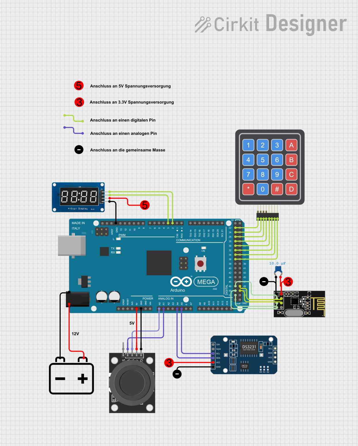


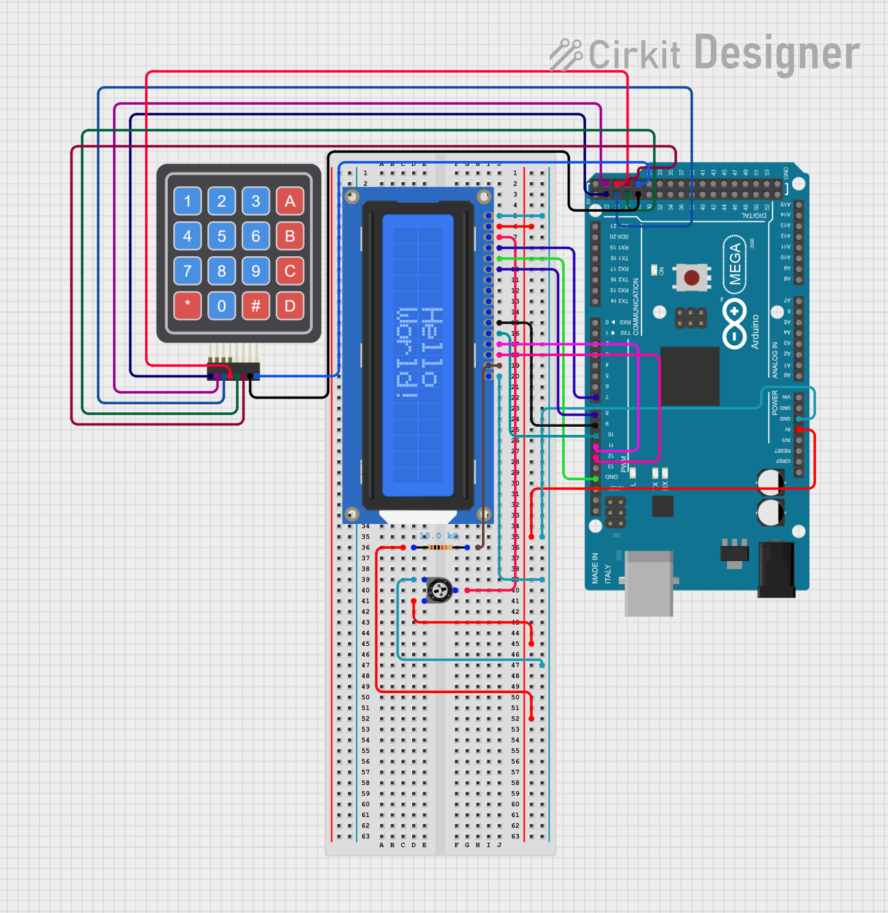
Explore Projects Built with 24LC256
Common Applications and Use Cases
- Data logging in embedded systems
- Configuration and calibration data storage
- Storing lookup tables or user preferences
- Firmware or program storage for microcontrollers
- Backup memory for real-time clock (RTC) modules
Technical Specifications
The 24LC256 is a versatile EEPROM with the following key specifications:
| Parameter | Value |
|---|---|
| Memory Size | 256 Kbit (32K x 8) |
| Interface | I2C (2-wire) |
| Operating Voltage Range | 2.5V to 5.5V |
| Maximum Clock Frequency | 400 kHz (Fast Mode I2C) |
| Write Cycle Time | 5 ms (typical) |
| Data Retention | > 200 years |
| Endurance | 1,000,000 write/erase cycles |
| Operating Temperature Range | -40°C to +85°C |
| Package Types | PDIP, SOIC, TSSOP, MSOP |
Pin Configuration and Descriptions
The 24LC256 is typically available in an 8-pin package. Below is the pinout and description:
| Pin Number | Pin Name | Description |
|---|---|---|
| 1 | A0 | Address input bit 0 (used for I2C slave address selection) |
| 2 | A1 | Address input bit 1 (used for I2C slave address selection) |
| 3 | A2 | Address input bit 2 (used for I2C slave address selection) |
| 4 | VSS | Ground (0V reference) |
| 5 | SDA | Serial Data (I2C bidirectional data line) |
| 6 | SCL | Serial Clock (I2C clock line) |
| 7 | WP | Write Protect (active HIGH; disables write operations when HIGH) |
| 8 | VCC | Power supply (2.5V to 5.5V) |
Usage Instructions
How to Use the 24LC256 in a Circuit
- Power Supply: Connect the VCC pin to a power source (2.5V to 5.5V) and the VSS pin to ground.
- I2C Connections:
- Connect the SDA pin to the microcontroller's I2C data line.
- Connect the SCL pin to the microcontroller's I2C clock line.
- Use pull-up resistors (typically 4.7 kΩ) on both SDA and SCL lines.
- Address Selection:
- Use the A0, A1, and A2 pins to set the I2C slave address. These pins can be tied to VCC or VSS to configure the address.
- The base address of the 24LC256 is
0x50. The full address is determined by the state of A0, A1, and A2.
- Write Protection:
- If write protection is required, set the WP pin HIGH. For normal operation, connect WP to ground.
Example: Connecting to an Arduino UNO
Below is an example of how to connect the 24LC256 to an Arduino UNO and write/read data.
Circuit Diagram
- Connect:
- SDA (pin 5) to Arduino A4
- SCL (pin 6) to Arduino A5
- VCC (pin 8) to 5V
- VSS (pin 4) to GND
- A0, A1, A2 to GND (for base address
0x50) - WP to GND (to enable write operations)
Arduino Code Example
#include <Wire.h> // Include the Wire library for I2C communication

#define EEPROM_I2C_ADDRESS 0x50 // Base address of 24LC256

void setup() {
  Wire.begin(); // Initialize I2C communication
  Serial.begin(9600); // Initialize serial communication for debugging

  // Write a byte to EEPROM
  writeEEPROM(0x0000, 42); // Write the value 42 to address 0x0000
  delay(10); // Wait for the write cycle to complete

  // Read the byte back from EEPROM
  uint8_t value = readEEPROM(0x0000);
  Serial.print("Read value: ");
  Serial.println(value); // Should print 42
}

void loop() {
  // Nothing to do here
}

// Function to write a byte to the 24LC256
void writeEEPROM(uint16_t address, uint8_t data) {
  Wire.beginTransmission(EEPROM_I2C_ADDRESS);
  Wire.write((address >> 8) & 0xFF); // Send the high byte of the address
  Wire.write(address & 0xFF);        // Send the low byte of the address
  Wire.write(data);                  // Send the data byte
  Wire.endTransmission();
  delay(5); // Allow time for the write cycle to complete
}

// Function to read a byte from the 24LC256
uint8_t readEEPROM(uint16_t address) {
  Wire.beginTransmission(EEPROM_I2C_ADDRESS);
  Wire.write((address >> 8) & 0xFF); // Send the high byte of the address
  Wire.write(address & 0xFF);        // Send the low byte of the address
  Wire.endTransmission();

  Wire.requestFrom(EEPROM_I2C_ADDRESS, 1); // Request 1 byte from EEPROM
  if (Wire.available()) {
    return Wire.read(); // Return the received byte
  }
  return 0xFF; // Return 0xFF if no data is available
}
Important Considerations and Best Practices
- Pull-Up Resistors: Ensure proper pull-up resistors are used on the SDA and SCL lines for reliable I2C communication.
- Write Cycle Time: Allow sufficient time (typically 5 ms) for write operations to complete before initiating another write or read.
- Address Conflicts: Avoid I2C address conflicts when using multiple devices on the same bus.
- Write Protection: Use the WP pin to prevent accidental overwrites in critical applications.
Troubleshooting and FAQs
Common Issues and Solutions
EEPROM Not Responding:
- Verify the I2C connections and ensure pull-up resistors are in place.
- Check the I2C address configuration (A0, A1, A2 pins).
- Ensure the power supply voltage is within the specified range.
Incorrect Data Read/Write:
- Ensure the write cycle time (5 ms) is respected before reading or writing again.
- Verify the address being accessed is within the valid range (0x0000 to 0x7FFF).
Write Operations Failing:
- Check if the WP pin is HIGH. If so, set it to LOW to enable writes.
FAQs
Q: Can I use the 24LC256 with a 3.3V microcontroller?
A: Yes, the 24LC256 operates within a voltage range of 2.5V to 5.5V, making it compatible with 3.3V systems.
Q: How many devices can I connect on the same I2C bus?
A: Up to 8 24LC256 devices can be connected on the same I2C bus by configuring the A0, A1, and A2 pins for unique addresses.
Q: What happens if power is lost during a write operation?
A: The data being written may be corrupted. It is recommended to use a power-fail detection circuit to handle such scenarios.