
How to Use DIP SOCKET IC 28 pin: Examples, Pinouts, and Specs
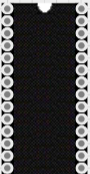
 Design with DIP SOCKET IC 28 pin in Cirkit Designer
Introduction
The DIP SOCKET IC 28 Pin (Manufacturer: CNC Tech, Part ID: 245-28-1-06) is a Dual In-line Package (DIP) socket designed to securely hold 28-pin integrated circuits (ICs). It provides a reliable interface between the IC and the circuit board, allowing for easy insertion, removal, and replacement of ICs without soldering. This component is widely used in prototyping, testing, and applications where IC replacement or upgrades are frequent.
Explore Projects Built with DIP SOCKET IC 28 pin
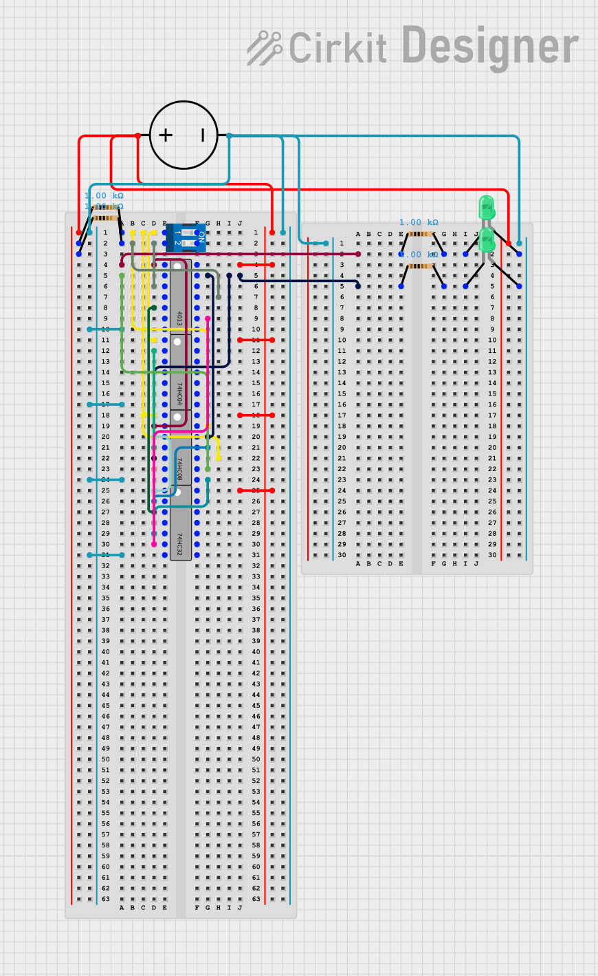 Open Project in Cirkit Designer
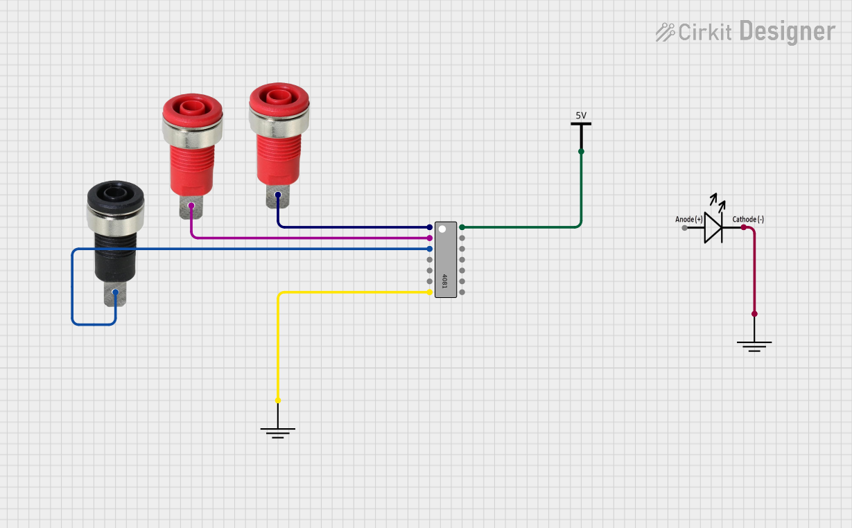 Open Project in Cirkit Designer
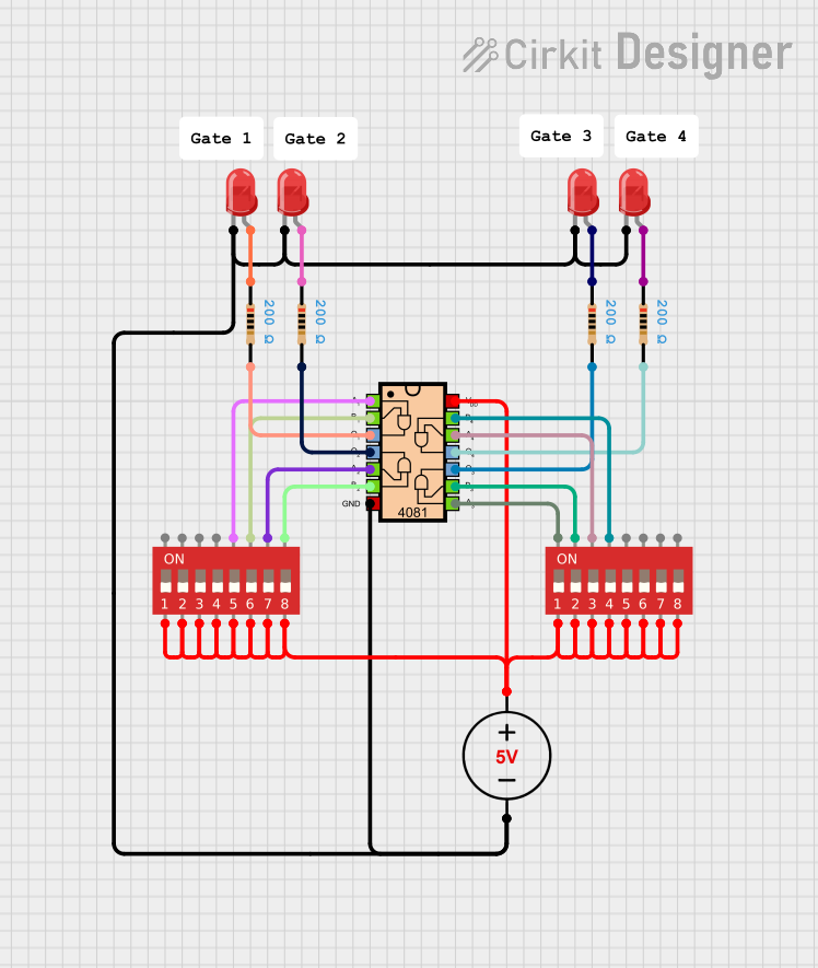 Open Project in Cirkit Designer
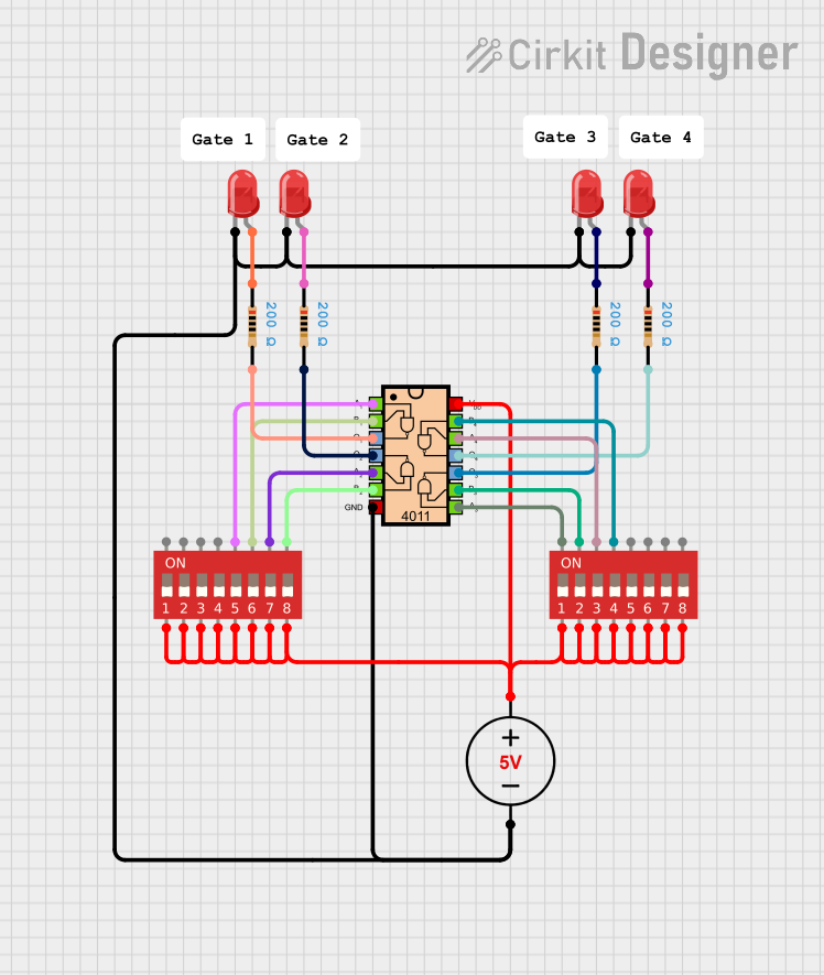 Open Project in Cirkit Designer
Explore Projects Built with DIP SOCKET IC 28 pin
Open Project in Cirkit DesignerOpen Project in Cirkit DesignerOpen Project in Cirkit DesignerOpen Project in Cirkit DesignerCommon Applications and Use Cases
- Prototyping and development of electronic circuits
- IC testing and debugging
- Protection of ICs from heat damage during soldering
- Applications requiring frequent IC replacement or upgrades
- Use in Arduino-based projects for IC interfacing
Technical Specifications
The following table outlines the key technical details of the DIP SOCKET IC 28 Pin:
| Parameter | Specification |
|---|---|
| Manufacturer | CNC Tech |
| Part ID | 245-28-1-06 |
| Number of Pins | 28 |
| Pin Pitch | 2.54 mm (0.1 inch) |
| Material | Thermoplastic (socket body) |
| Contact Material | Phosphor Bronze |
| Contact Plating | Tin |
| Operating Temperature | -40°C to +105°C |
| Mounting Type | Through-hole |
| Dimensions (L x W x H) | 35.56 mm x 7.62 mm x 5.08 mm |
Pin Configuration and Descriptions
The DIP SOCKET IC 28 Pin is designed to accommodate ICs with a standard 28-pin configuration. The pin layout corresponds directly to the IC pins, with a 2.54 mm pitch between adjacent pins. Below is a general description of the pin configuration:
| Pin Number | Description |
|---|---|
| 1-28 | Direct connection to IC pins. Each pin corresponds to the IC pin layout. |
Usage Instructions
How to Use the DIP SOCKET IC 28 Pin in a Circuit
- Prepare the PCB: Ensure the PCB has a 28-pin through-hole footprint with a 2.54 mm pitch that matches the DIP socket.
- Insert the Socket: Place the DIP socket into the PCB, aligning the pins with the holes. Ensure the notch on the socket aligns with the IC orientation marking on the PCB.
- Solder the Pins: Solder each pin of the socket to the PCB pads. Use a soldering iron with a fine tip for precision.
- Insert the IC: Align the IC pins with the socket and gently press the IC into place. Ensure the IC orientation matches the socket notch.
- Connect to Circuit: Wire the PCB connections to the rest of the circuit as required.
Important Considerations and Best Practices
- Orientation: Always align the notch on the socket with the IC orientation marking to avoid incorrect placement.
- Soldering: Avoid excessive heat during soldering to prevent damage to the socket or PCB.
- IC Insertion/Removal: Use an IC extractor tool to prevent bending or damaging the IC pins.
- Compatibility: Ensure the IC pin count and pitch match the socket specifications.
Example: Using with an Arduino UNO
The DIP SOCKET IC 28 Pin can be used to interface ICs like the ATmega328P (commonly used in Arduino UNO). Below is an example of how to blink an LED using an ATmega328P in a DIP socket:
// Example code for blinking an LED using ATmega328P in a DIP socket
// Connect the ATmega328P to the DIP socket and ensure proper wiring
// Pin 19 (PB5) is connected to the LED with a resistor

void setup() {
  pinMode(13, OUTPUT); // Set digital pin 13 (PB5) as output
}

void loop() {
  digitalWrite(13, HIGH); // Turn the LED on
  delay(1000);            // Wait for 1 second
  digitalWrite(13, LOW);  // Turn the LED off
  delay(1000);            // Wait for 1 second
}
Troubleshooting and FAQs
Common Issues Users Might Face
IC Not Functioning Properly:
- Cause: Incorrect IC orientation or poor contact between IC pins and socket.
- Solution: Verify the IC orientation matches the socket notch. Ensure all pins are properly seated.
Bent or Damaged Pins:
- Cause: Improper IC insertion or removal.
- Solution: Use an IC extractor tool for removal. Straighten bent pins carefully with tweezers.
Cold Solder Joints:
- Cause: Insufficient heat or solder during socket installation.
- Solution: Reheat the solder joints and apply additional solder if necessary.
Loose Socket Pins:
- Cause: Excessive force during IC insertion or removal.
- Solution: Replace the socket if pins are damaged or loose.
FAQs
Q1: Can this socket be used for ICs with fewer than 28 pins?
A1: Yes, but ensure the IC pins align with the corresponding socket pins. Unused pins will remain unconnected.
Q2: Is this socket compatible with surface-mount ICs?
A2: No, this socket is designed for through-hole DIP ICs only.
Q3: How do I clean the socket if it gets dirty?
A3: Use compressed air or a soft brush to remove debris. Avoid using liquids that may damage the contacts.
Q4: Can I reuse the socket after desoldering it from a PCB?
A4: Yes, but ensure the pins are not damaged during desoldering. Clean the pins before reuse.